Open Claw
the june build
It was time to have another go at the challenge of creating a large scale tensegrity which could be used and moved from one location to the next.
Starting about the beginning of the year, we got serious about building this object, which looks a bit like a claw.
Of course I first modeled it on the computer and with ENS Engineers did all the numbers, designs of parts, and optimization of the tools and techniques.
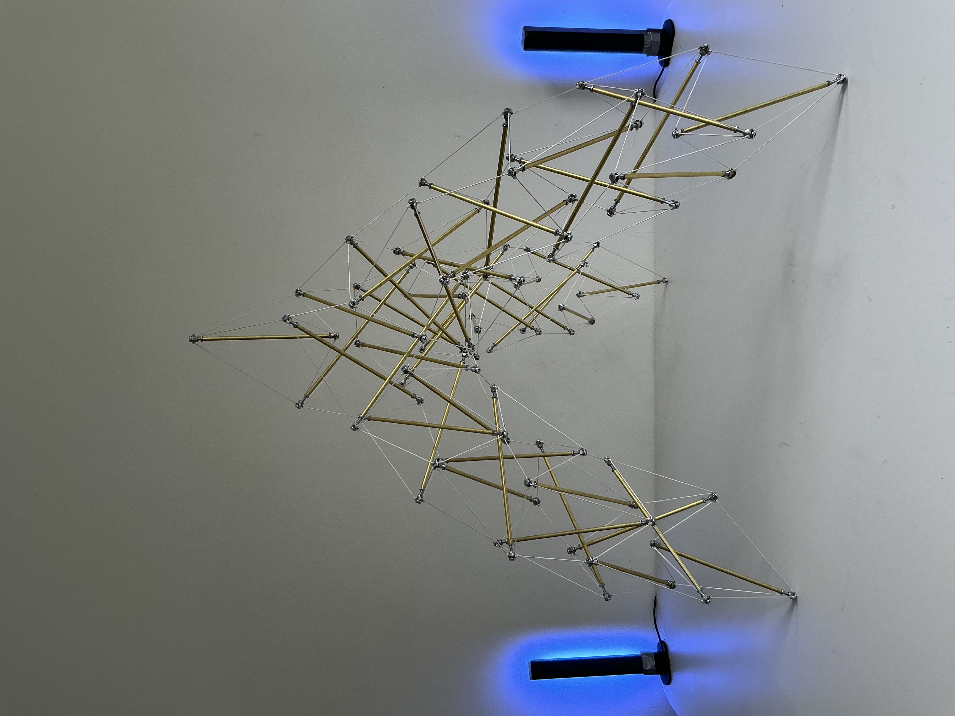
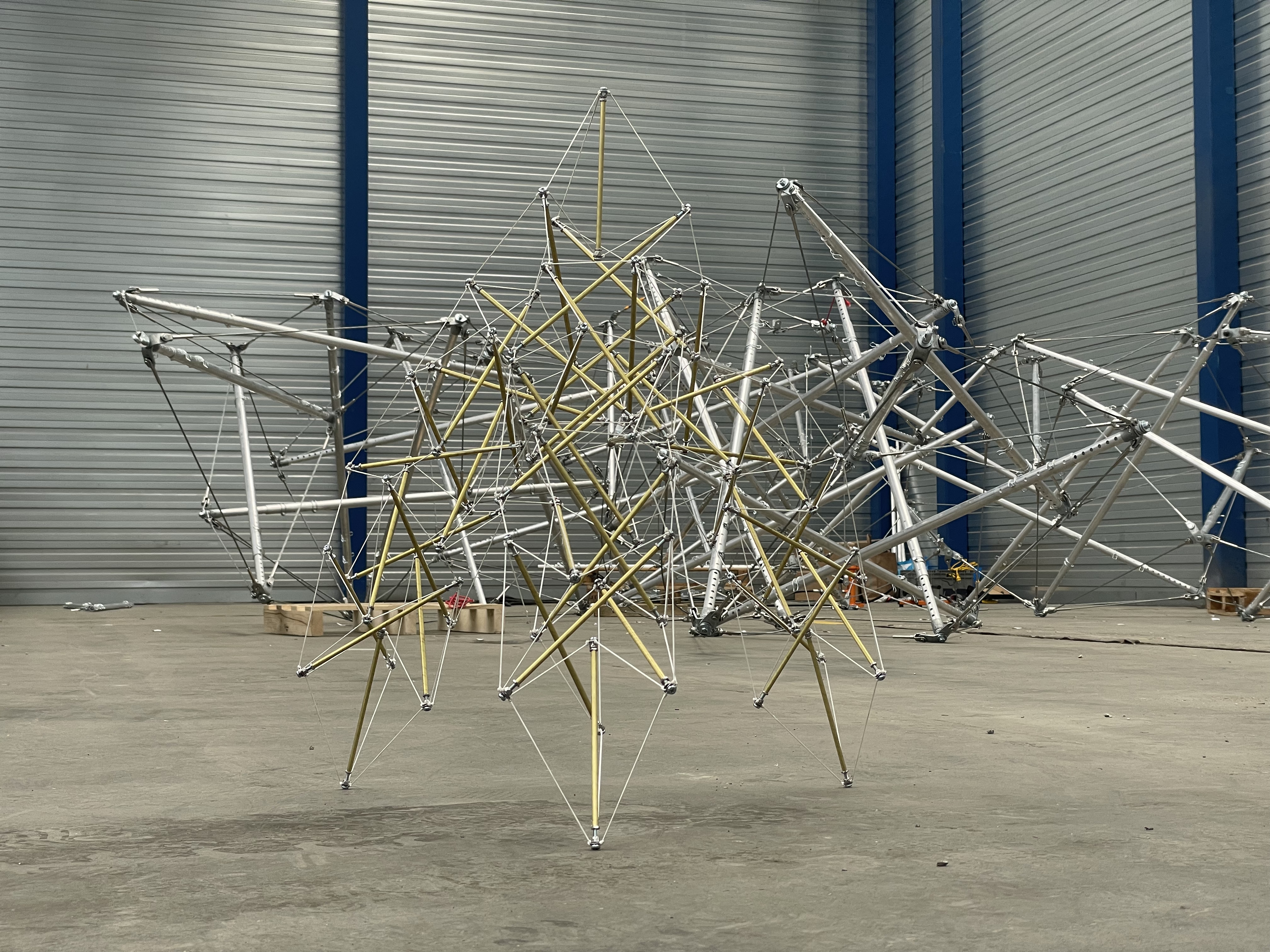
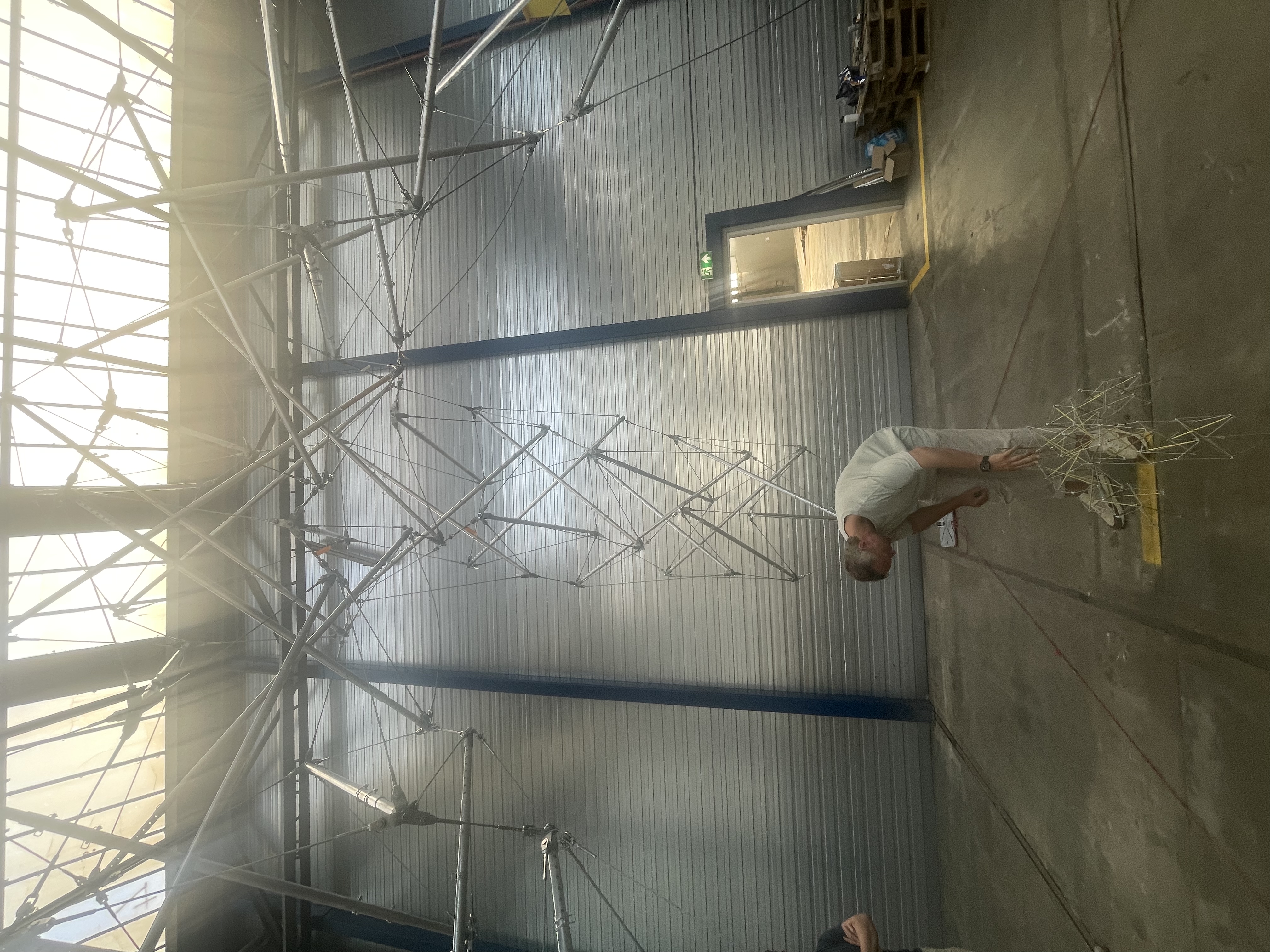
Then, in May, anticipating the building of the real thing in June, I built this 1:10 version. I knew from experience that a scale model would be indispensable during the actual build of the full scale version.
With the festival opening in the beginning of July, we needed to have a good part of June for the build, because there was a lot of preparation to do, and all the parts had not yet arrived.
Tuesday 2 June — aluminum struts
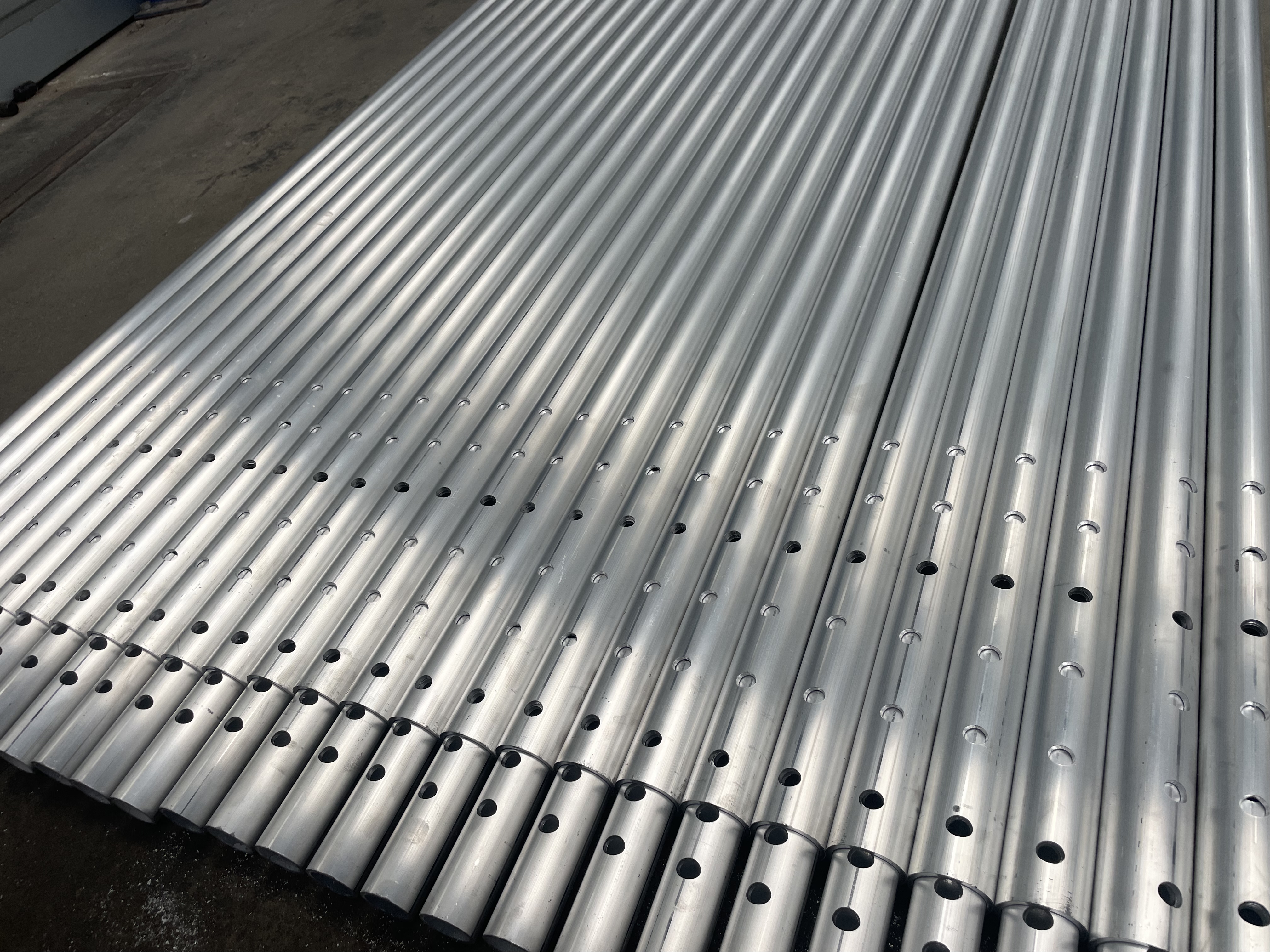
The first thing to arrive was the aluminum struts, or actually the parts, because for each strut there is an outer tube and an inner tube, both with holes cut by laser at strategic locations.
The system was such that you could count the number of visible holes, and then still have three different pairs of lined-up holes for three in-between lengths. This allowed for lengthening in steps of 10mm. First thing I did was to assemble all the telescoping struts, making sure of course that there were 46 and two spares.
Wednesday 3 June — strut prep, against the book
I had generated the geometry to pass on to the engineers in the form of a CSV file containing all of the coordinates including the intricate geometry of the caps which you will see below.
This CSV file became the foundation for the remainder of the project, since all of the relevant information was contained. I enlisted the AI to generate a book for me on the basis of the CSV, and it needed to contain all of the information required to build.
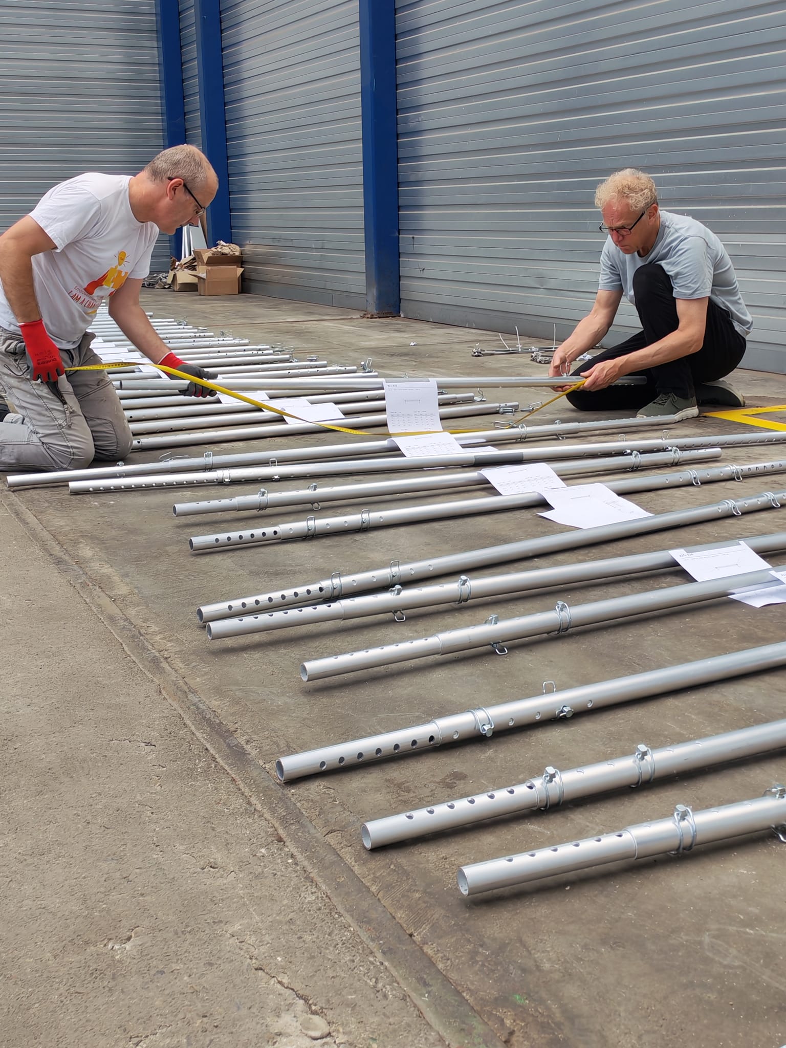
It has to puzzle out the geometry of each cap and give precise instructions about how to assemble them, and it also contained all of the strut lengths and the connections of the cable network, so I decided to stick one page of the book to each strut.
Each page had the length, and a complete spec of how to assemble the two caps.
Kees Jan and I adjusted them all to a rounded off length of Millimeters to the nearest hole combination.
Friday 5 June — a run to Belgium
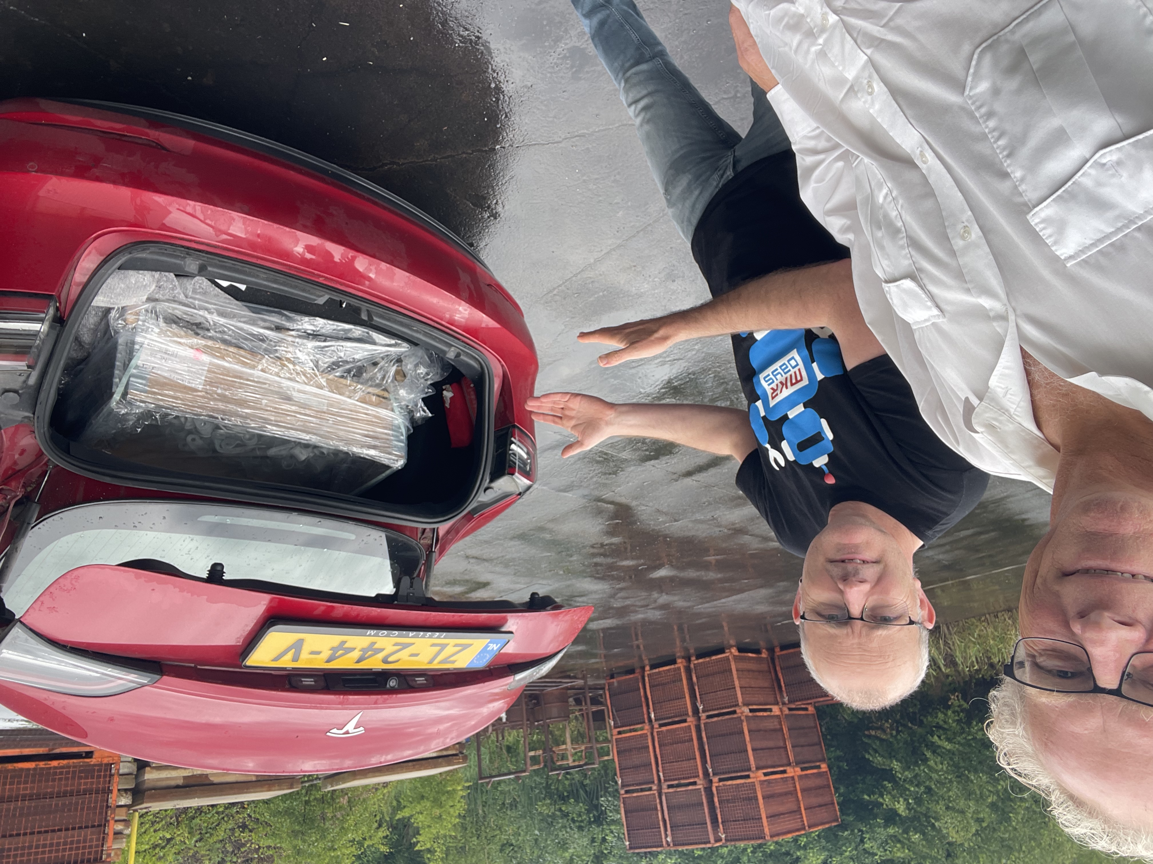
So we had the struts, and the steel end caps had been welded together, but now they needed to be galvanized. The only available location for galvanizing such a large number of small parts was in the south of Belgium, so we had to plan a road trip. We needed every available day, so we could not let it be transported, which would have taken a few more days.
Thankfully Kees Jan was up for a road trip to the galvanizer and we picked it up so we could get busy as soon as possible.
Saturday 6 June — preparing the joints
Two jobs before any of it could go into the structure: clean the threads, and label every part.
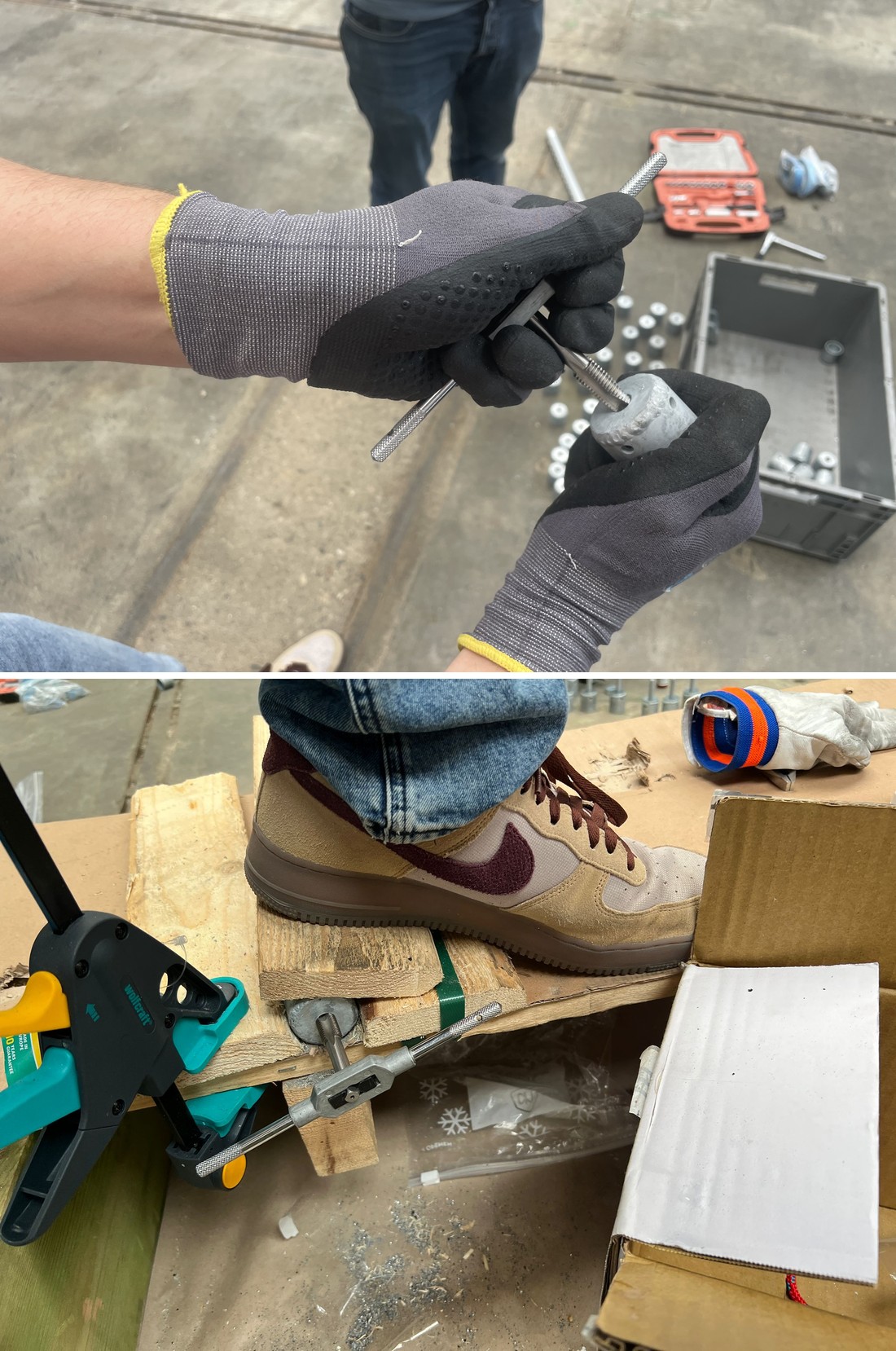
Galvanizing apparently fills the threads, so each cap was run through a tap to clear them. Peter went above and beyond the call of duty when he was persistent enough to tap all 92 caps in one day. It was hard physical work and sometimes difficult enough that he had to clamp it down with his foot to get a sufficient grip. For an engineer, he ended the day with a good number of blisters on his hand.
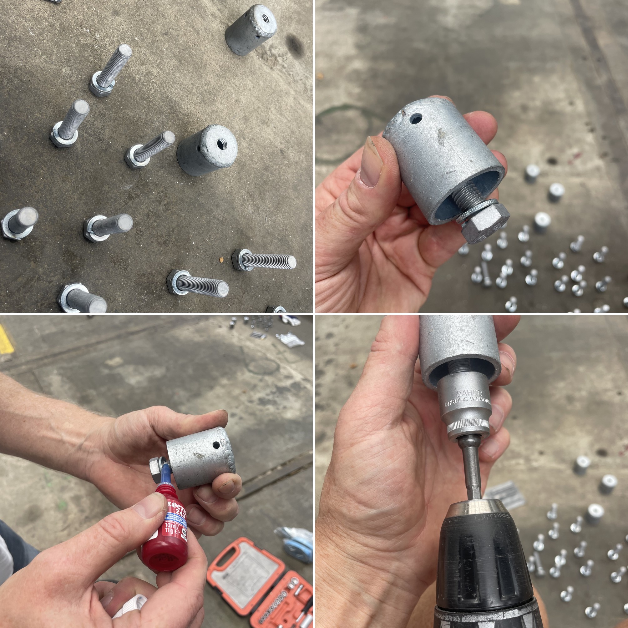
With each inner thread of the cap tapped clean, we could insert the bolts with a locking ring, add a bit of fixing goo, and turn them in so that the end of the bolt came out the other side. They would never have to be loosened again.
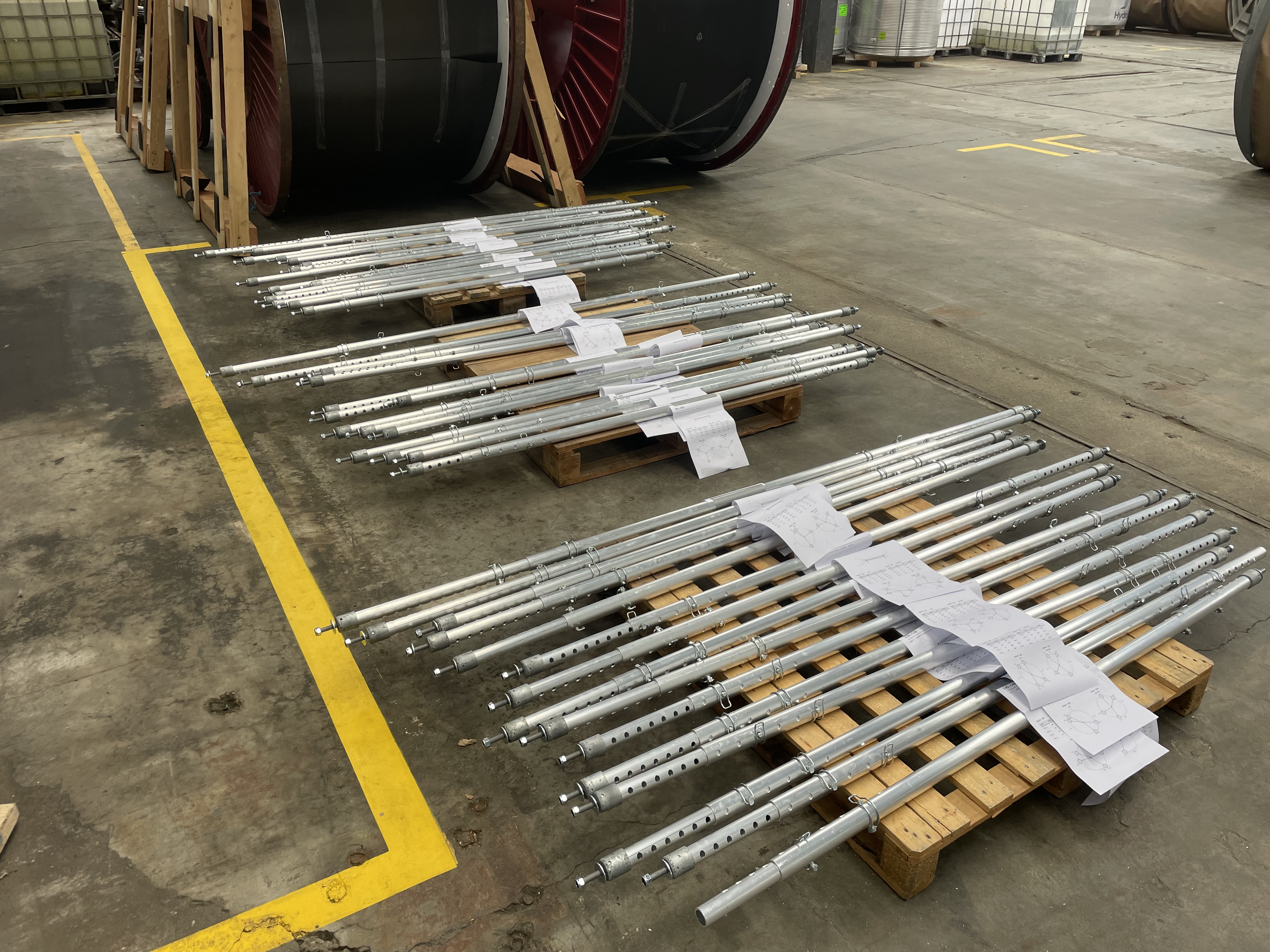
We put the caps on the ends of the struts and set about the process of labeling them all. I decided that absolutely everything about the geometry/topology of the object needed to be embedded in the materials of the object itself.
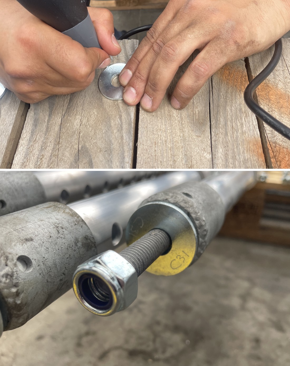
We discovered that it was much easier to engrave the joint names into the final ring at the end of each bolt, mostly because engraving a flat surface is easier than a cylindrical surface, but also because they were shiny so the engraving was more readable.
It also allowed us to “rename” caps by swapping their rings, and to my surprise this actually became necessary at one point.
Here you can see the engraving of joint “C31”.
Monday 8 June — assembling the caps
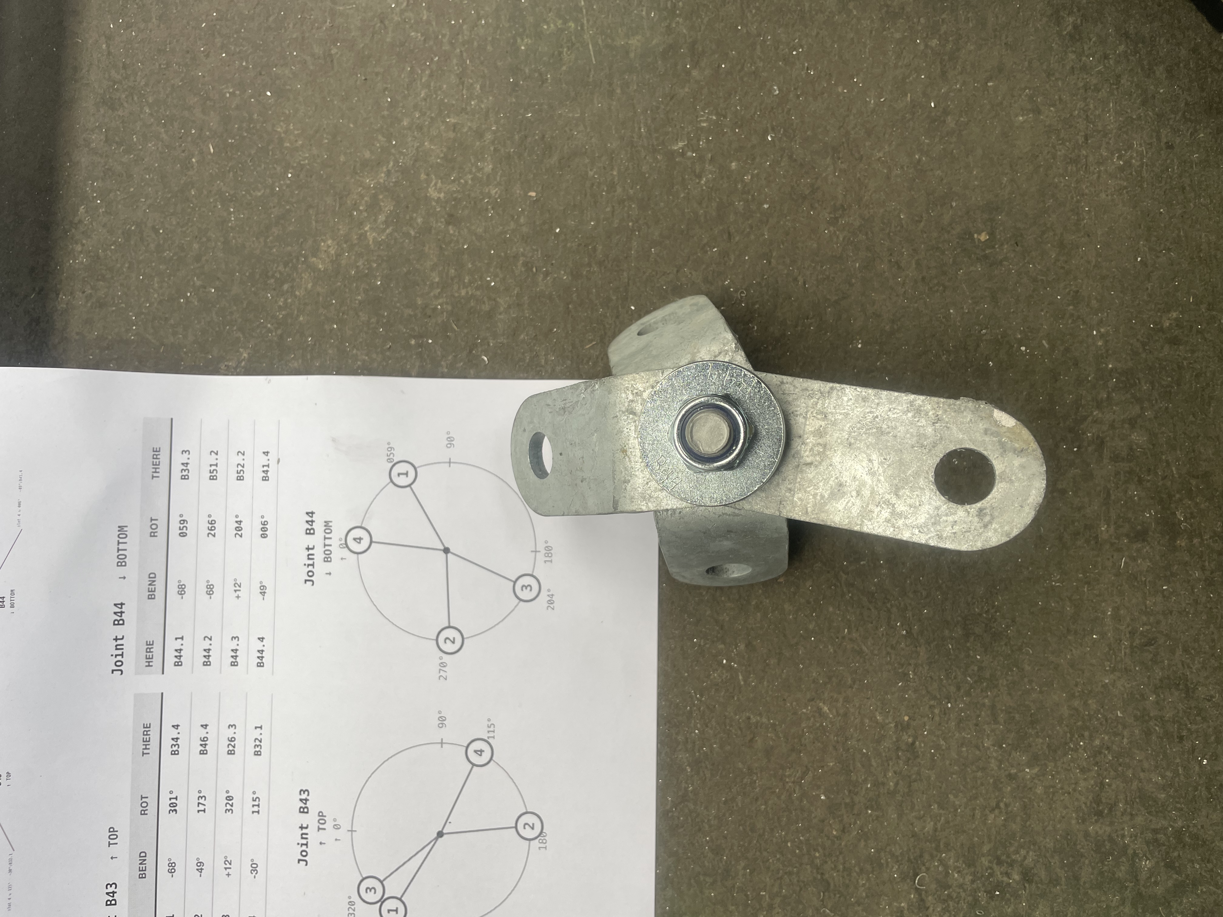
I arrived at the warehouse to spend a day working on it alone, and since all of the galvanized steel parts had arrived, I was able to take a good part of the day to properly assemble each of the 92 caps. (in the end I made a mistake only with one of them).
My building book generator, written by the AI, read the CSV file and puzzled out the geometry of each of the caps, indicating which angle of disk was required at each position on the stack, as well as the various angles that the disks would have to be at in the end shown in a kind of “clock” diagram.
Tuesday 9 June — caps done, bottom cables in
All caps completed and placed back on their respective struts.
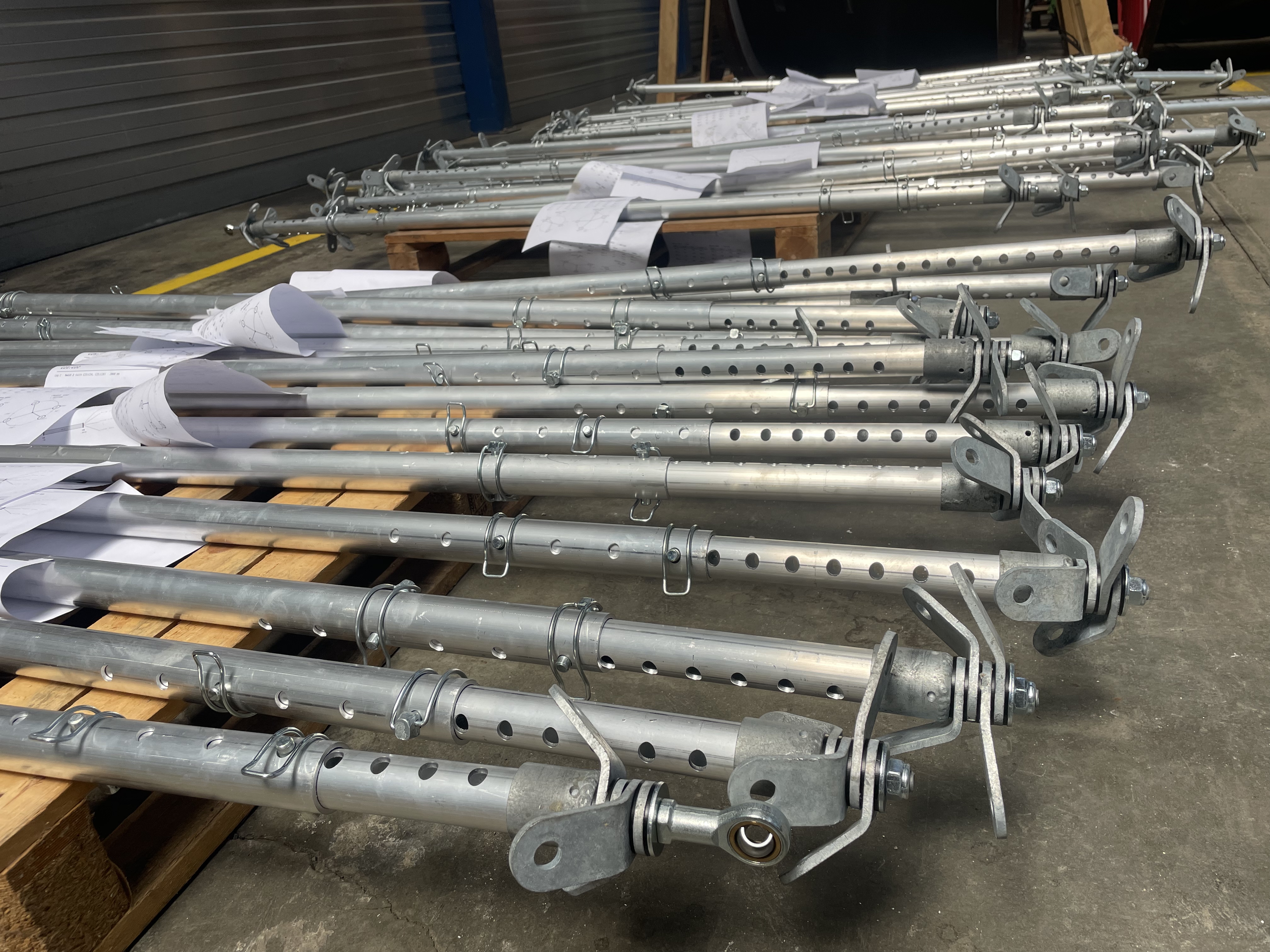
The first cable delivery came in, which had been (on request) the “lowest” in the structure, so that we could potentially start assembling the bottom parts.
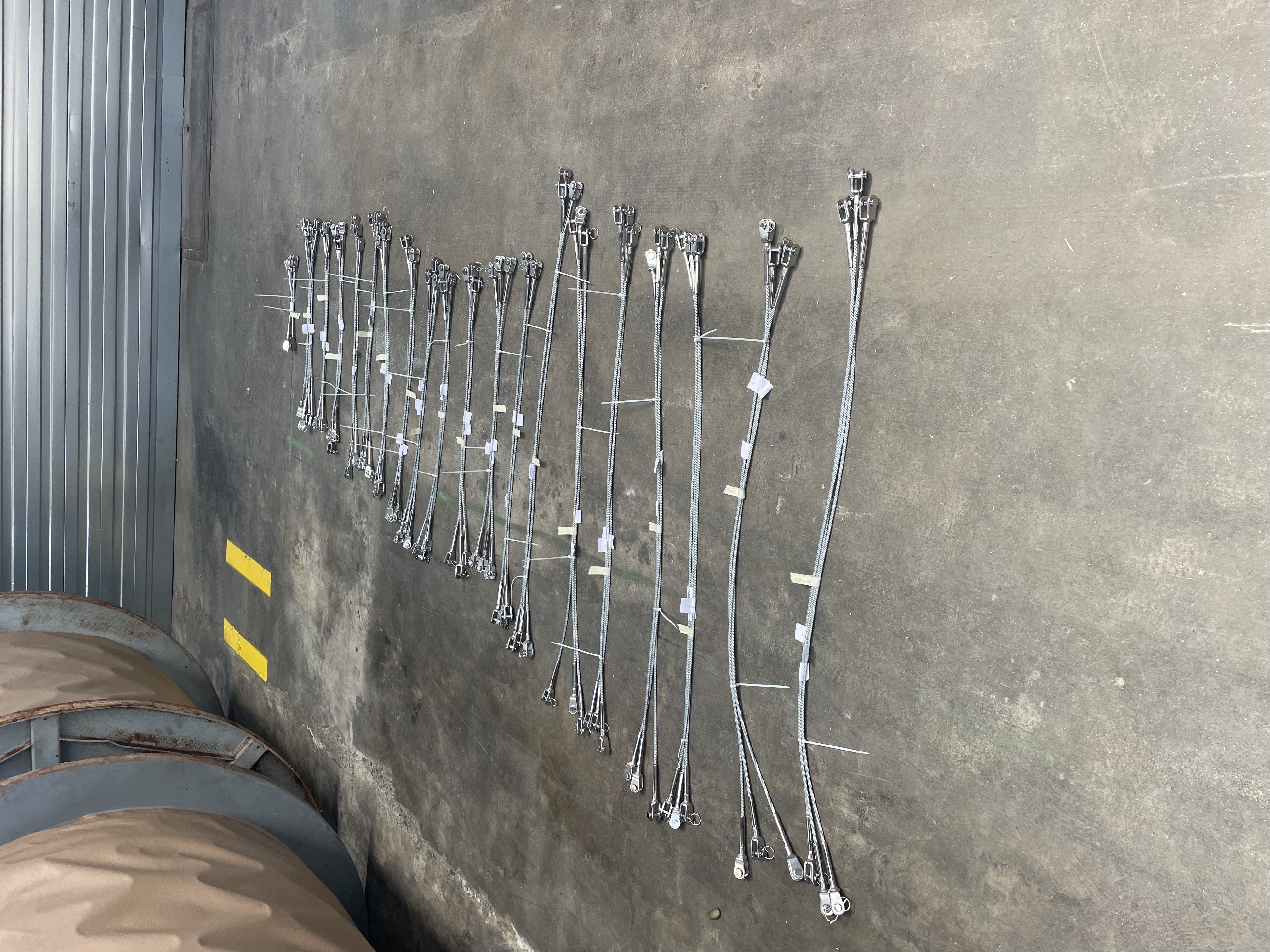
They were labeled with millimeter lengths but they still had to be engraved so that it is unambiguous where each and every cable belongs.
Wednesday 10 – Friday 12 June — building the cable network
All 46 struts, each with their own stories and with their caps completed and tightened up. Aside from the cables, this is everything.
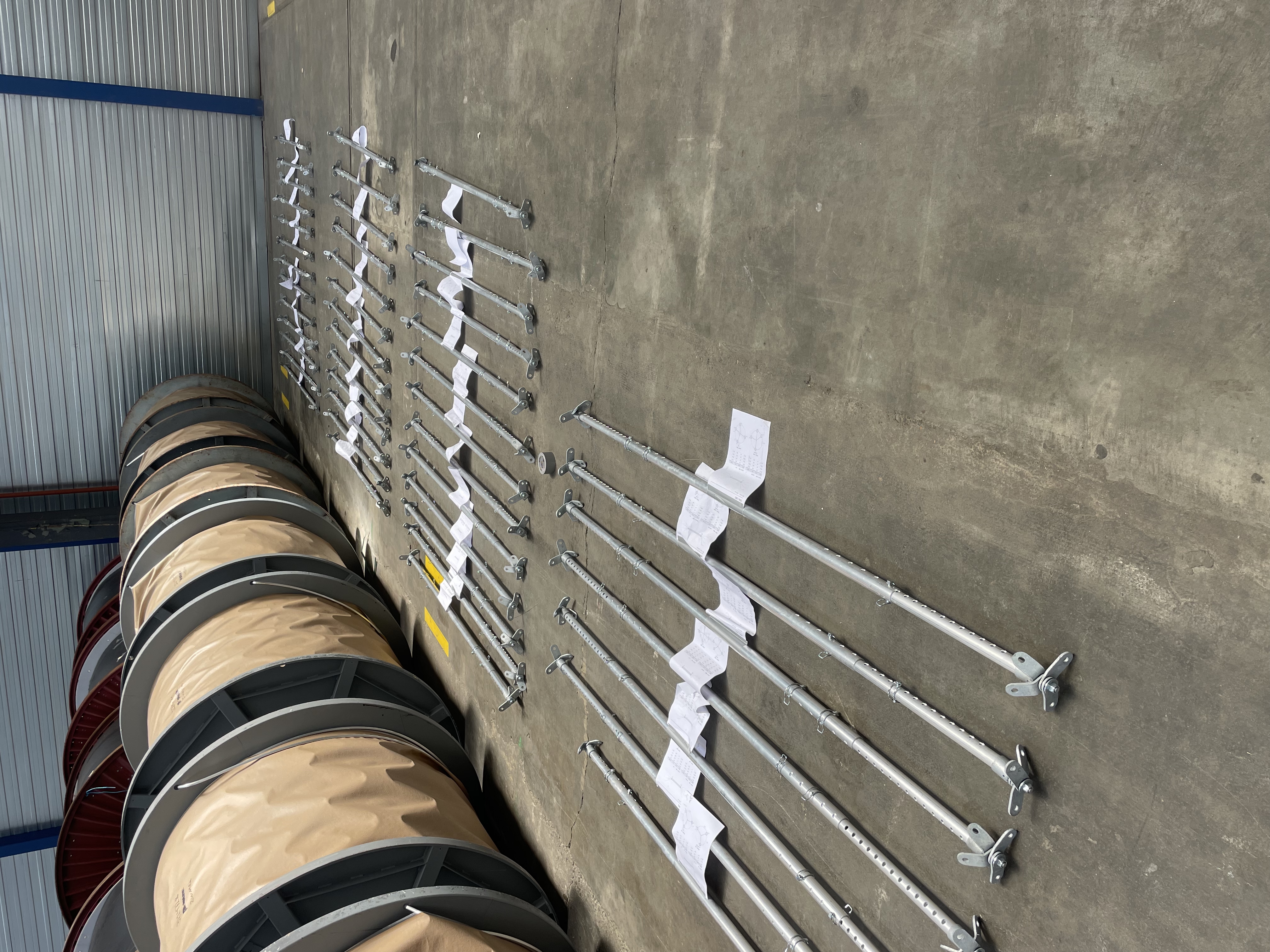
What I still ended up doing was writing information on the inner side of the connector disks. I needed it to be obvious, once you have found a cap, what the other cap’s name is so you know where to insert a strut.
Also, a number was added which indicated how many holes that the bar needed to be extended at that end. This was another step towards having the geometry information fully embedded in the material of the structure itself.
Custom tool
Lengthening struts involves pushing outward against quite a bit of force in order to expose the next hole so that the pin can be set one step further than it was. This is impossible to do by hand so we developed two tools for the job.
This tool rests on the collar of the wider tube and then pushes on a pin stuck through the holes of the narrower tube. With a strongly levered arm action you can easily lengthen by another hole or two in most circumstances although you really need two people for this.
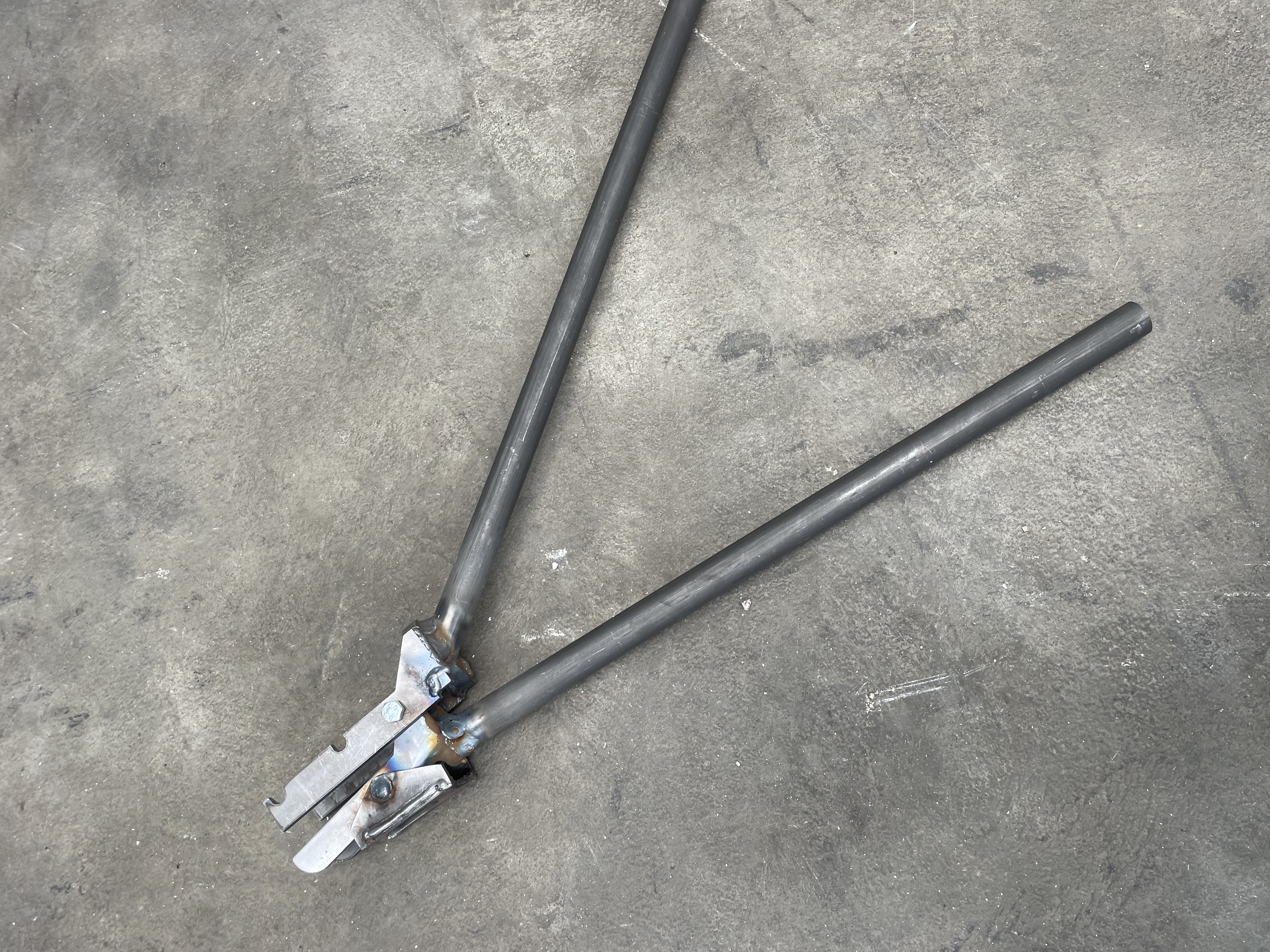
We attempted to figure out how to connect the hub portion where the legs come together, but it turned out to be much more difficult that we expected.
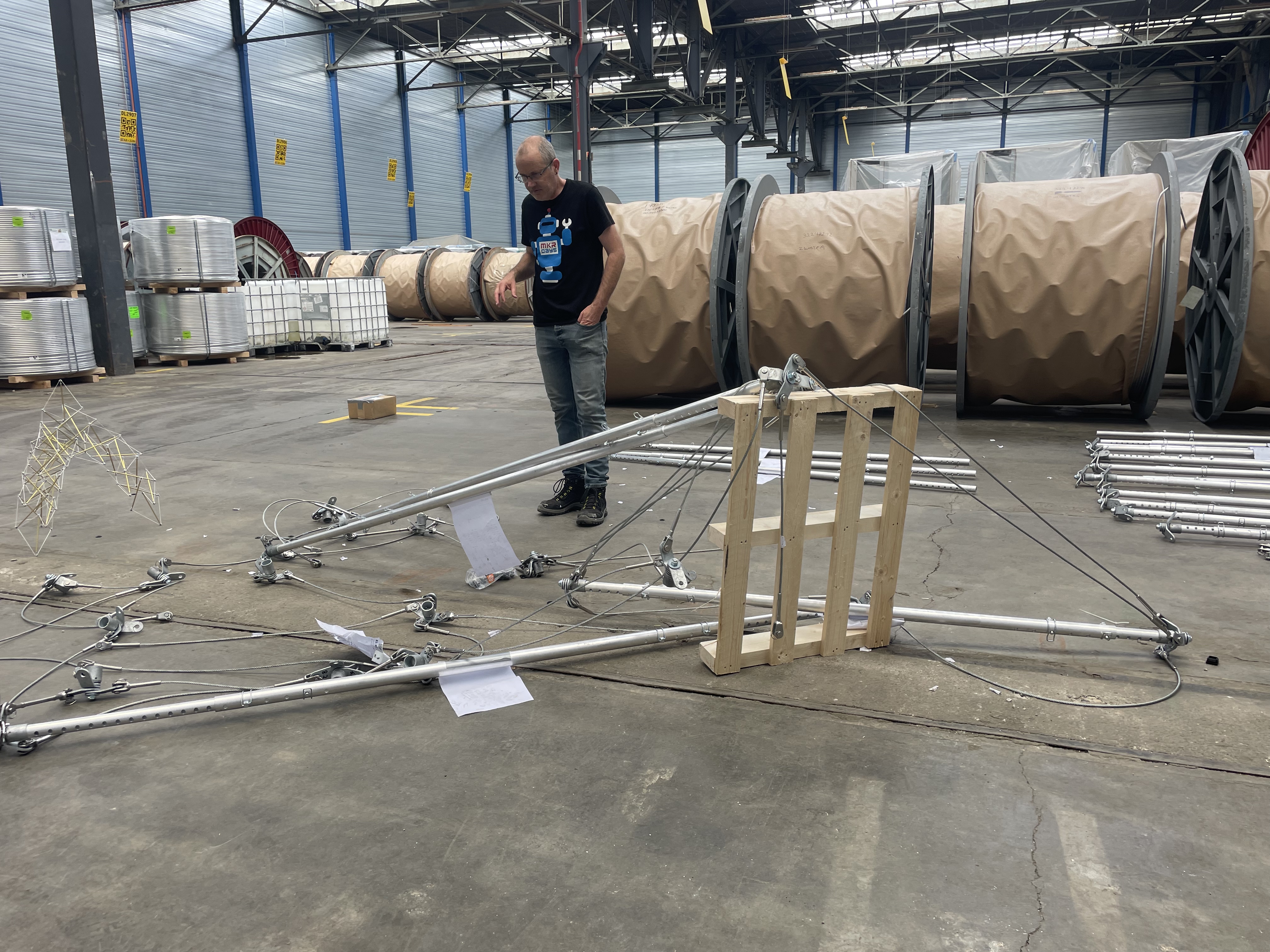
All of the 360 cable endpoints also needed to be engraved with labels indicating both which joint as well as which disk to connect with. I spent the rest of the day after Kees Jan left doing all of the puzzling with all of the cables, so that every endpoint had a written label and from that point on engraving became a no-brainer.
The following day I came back and did part of the engraving, and Jame was able to do a lot of it as well.
Saturday 13 June — the “Barn Raising”
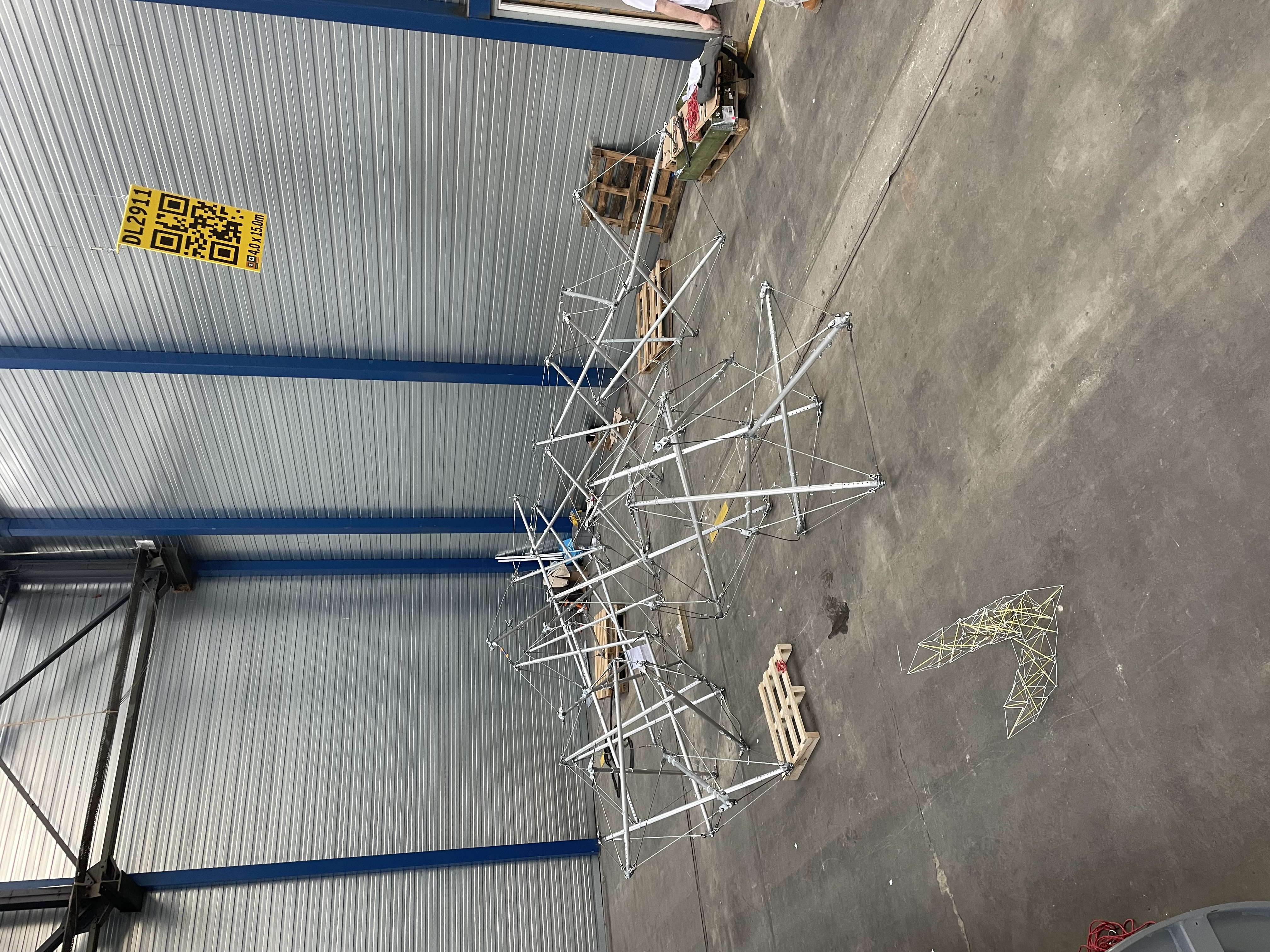
There were 360 cable connections to be made, and 46 struts to be inserted, so we assembled a team to make the process quick, hopefully just one day. All of the preparations from the previous week were leading up to this event, and every possible source of confusion that could be removed was removed.
There was enough left over, because it can be tricky to not accidentally build the cable network inside-out, and although this becomes clear enough when struts are inserted, it’s hard to know beforehand what is the right way to connect.
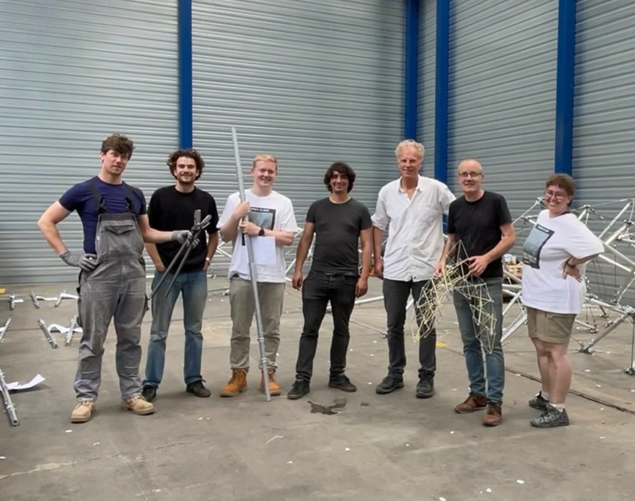
The crew was Peter, Sil, Joel, Adnan, me, Kees Jan, and Jame.
During the initial building, we referred constantly to the 1:10 scale model (and a couple of times to the software). The engraved IDs on every cap and cable worked perfectly. A couple of minor disc-stacking slip-ups I had made were picked out and corrected on the spot.
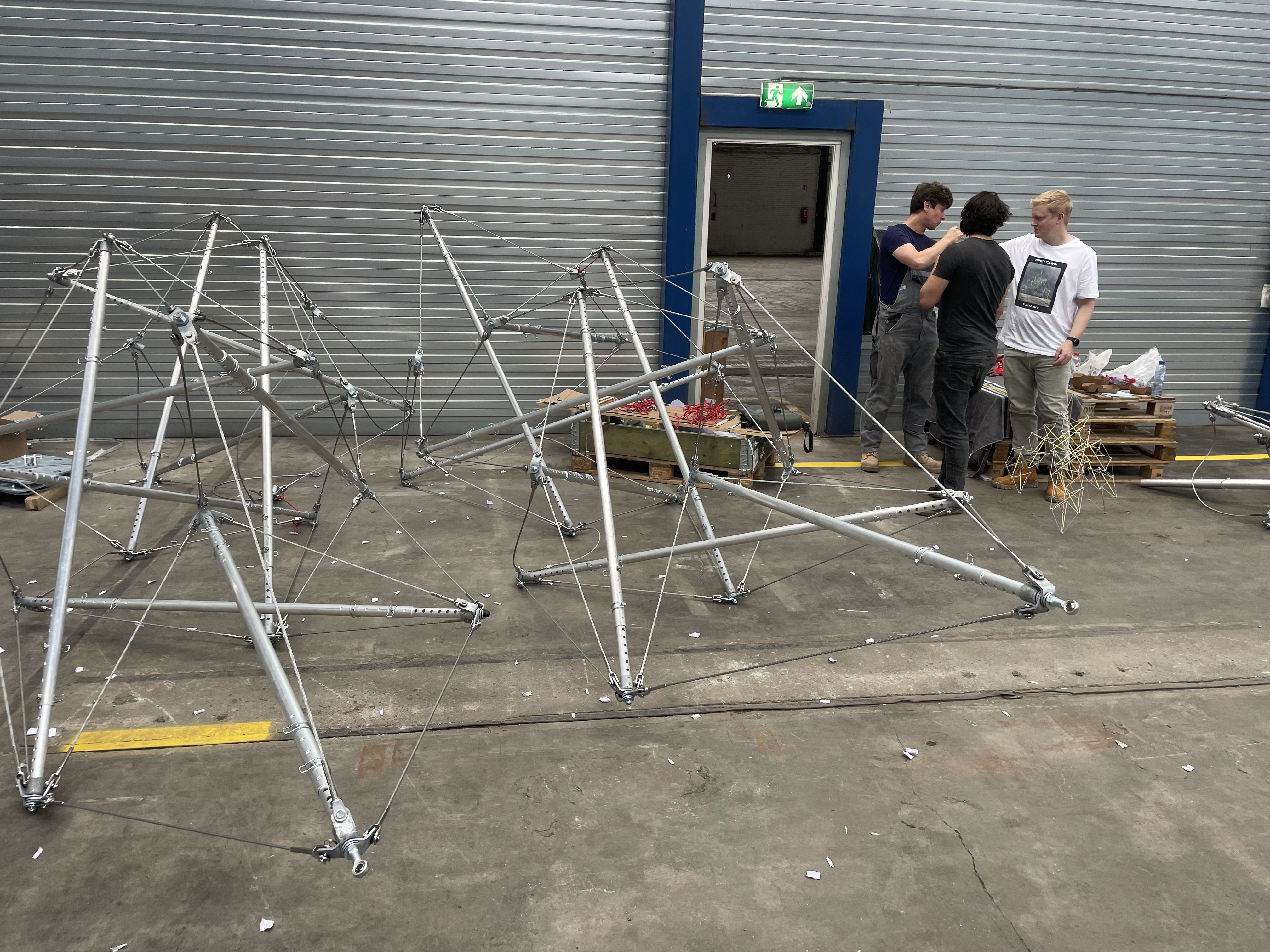
By the end: all three legs and the hub built, two legs connected — the third leg needs a crane to be lowered into place. Pizza (nobody wanted to stop), the new T-shirts worn, drinks and snacks, and a full-day time-lapse plus short interviews (all Jame).
Monday 15 June — tensioning the web
I came in for some hours alone to inspect and make the best preparations possible for the next phase, which would be connecting the third leg. I marked some things to highlight the symmetry, corrected a couple of things, and attached all 6 cables which would have to be connected once the third leg was suspended above.
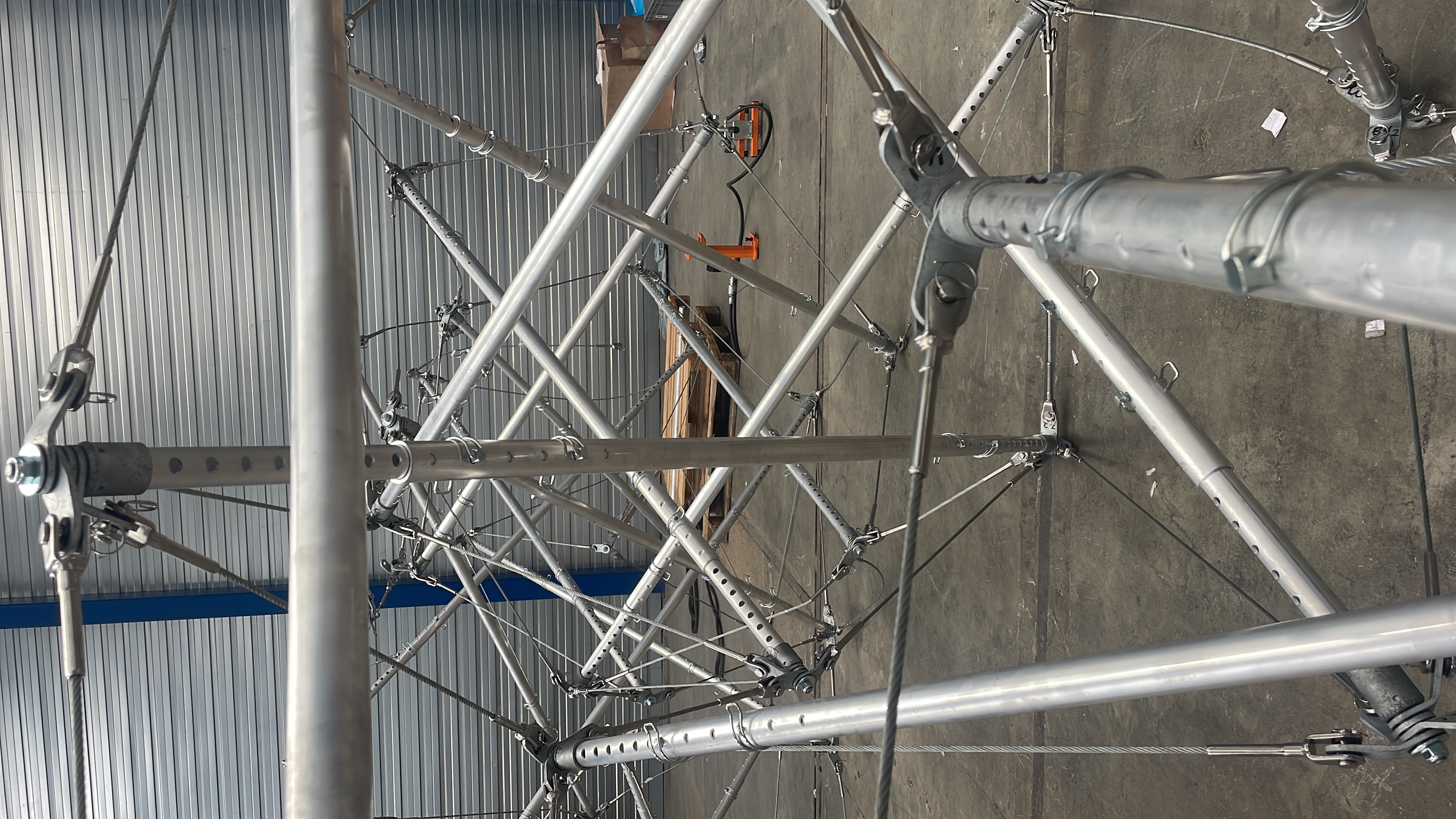
It’s hard to believe that it actually exists now at scale, although not quite finished. I keep comparing to the 1:10 model I had made as a guide.
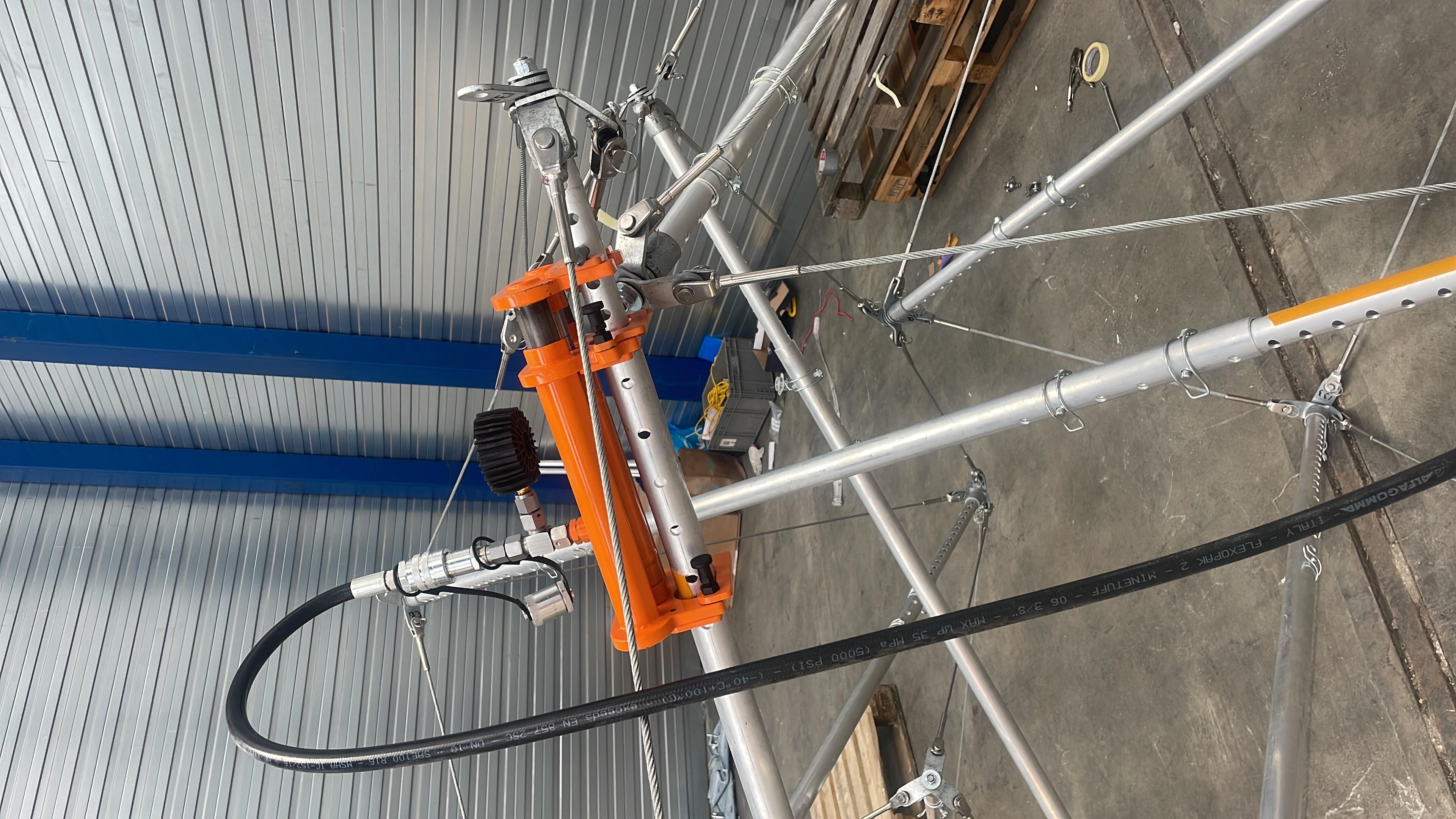
While making corrections, I was able to use the more advanced tensioning tool that I had commissioned, and this one uses hydraulic force. It is intended for the very last tightening that the tensegrity will need in the end, but since I was alone it also became useful for restoring struts that I had to shorten while making cable connections. I was able to lengthen a strut on my own!
Wednesday 17 June — the last leg
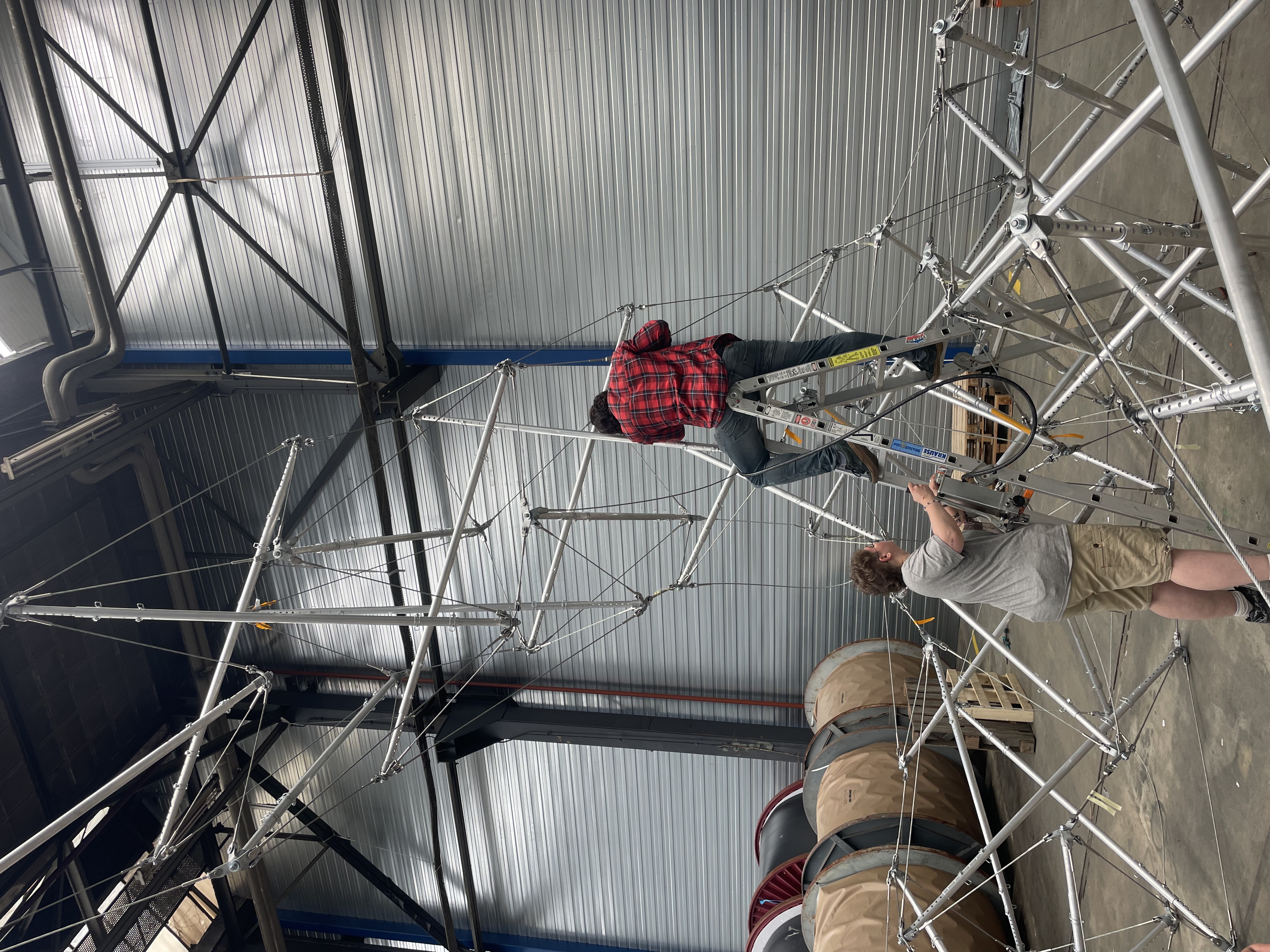
With help from the Zwatra people we were able to suspend the leg above the position that it was to be attached. Six cables connected, and three struts inserted, however we could of course not insert the struts at their specified length. We had to shorten them to get them in and then lengthen them afterwards with the hydraulic tool.
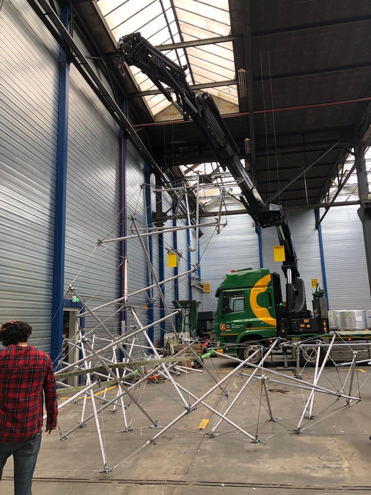
Then with the help of the expert Zwatra Transport team we were able to carefully attach a crane to the hub section and lift the structure up onto its feet!
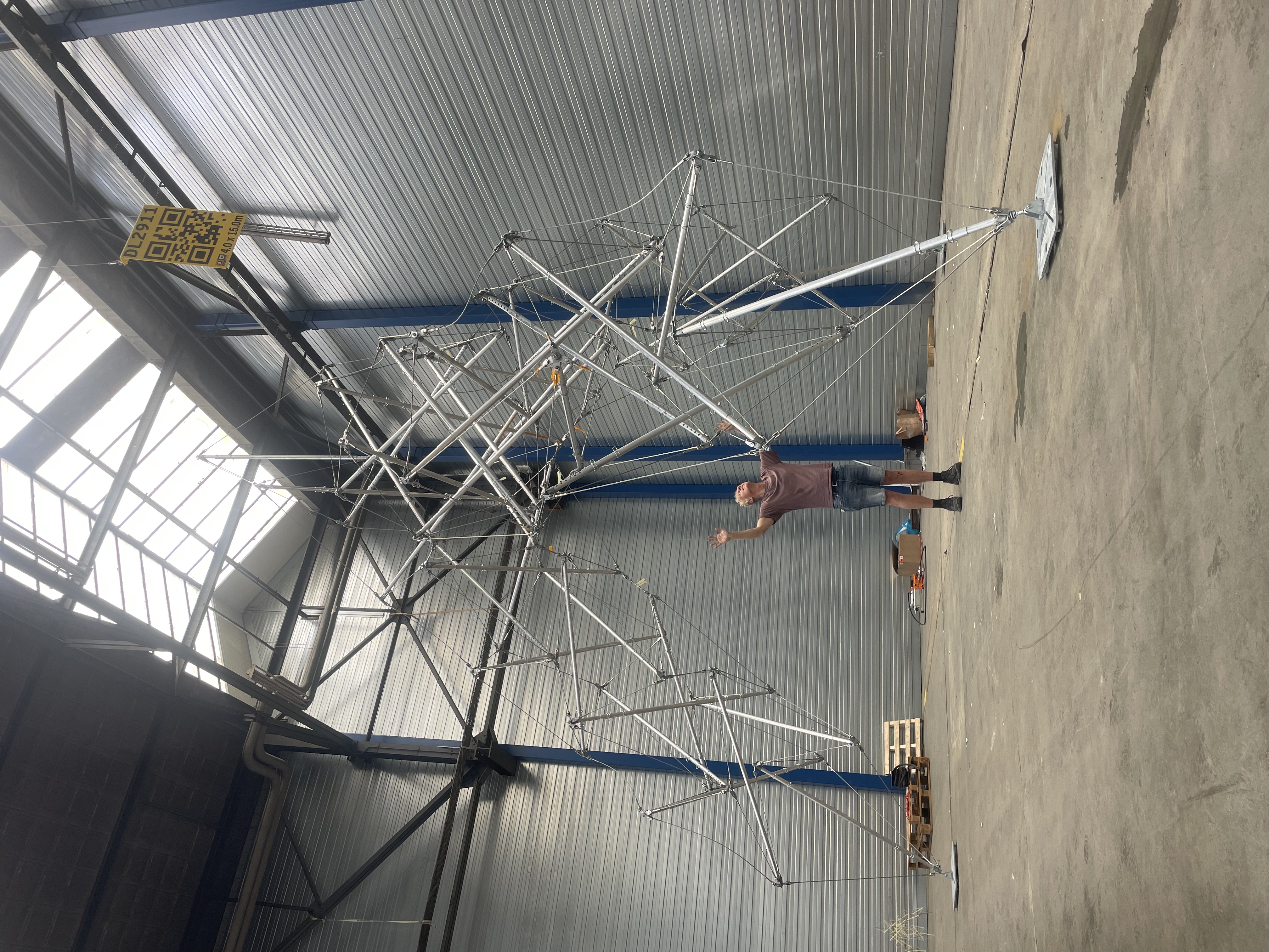
I was staring in disbelief that it was standing and looking solid after all those months of preparation! We spent some time tightening up the structure by lengthening a few strategic struts.
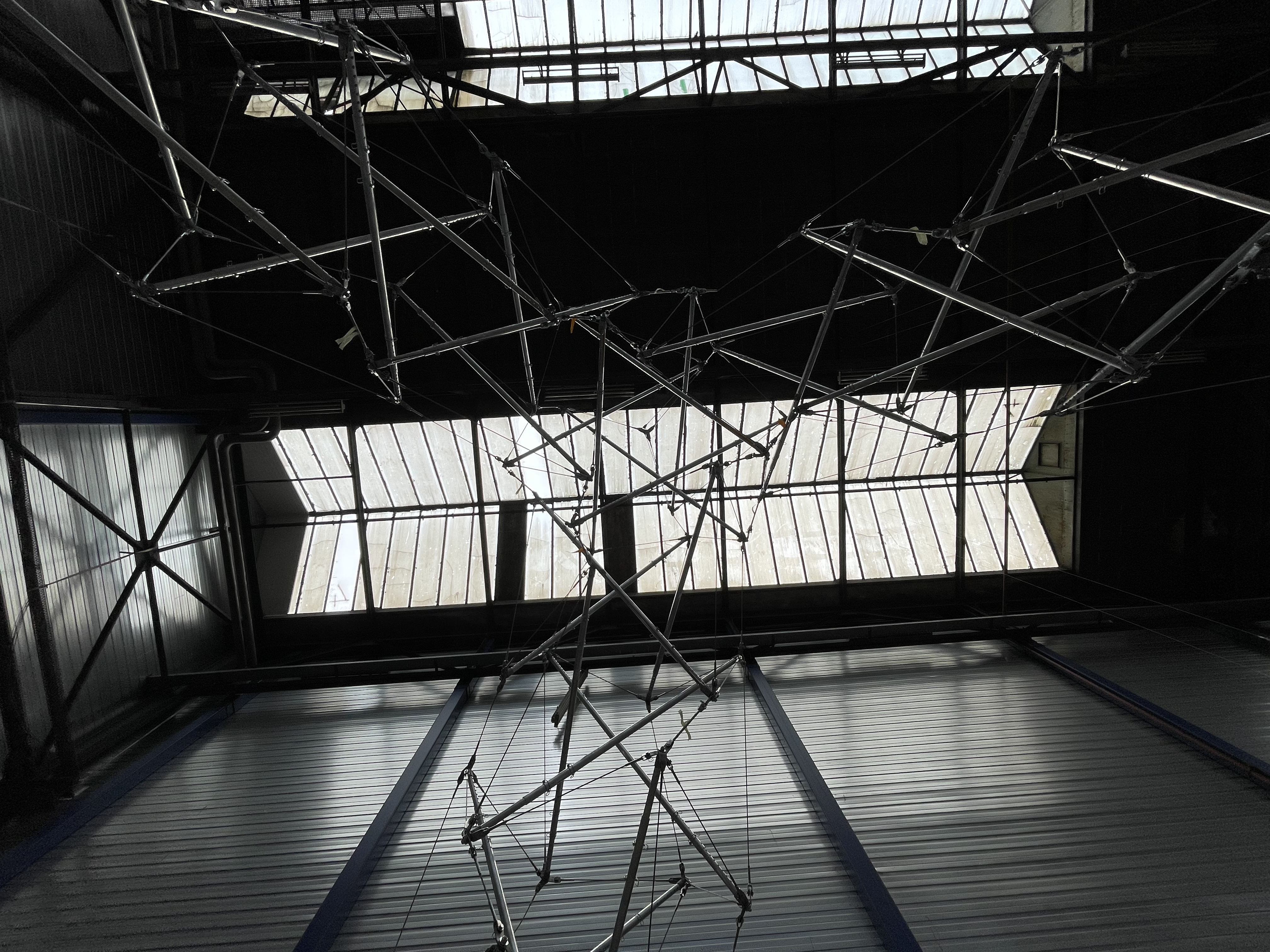
This was what you saw if you looked up.
Tuesday 23 June — a civil engineer comes to look
My friend and civil engineer Joel Keijnemans gave the object a good inspection and shared his impressions. He was generally very positive.
Thursday 25 June — taking it down
The Zwatra crew helped lift the object for disassembly. I had made a simulation of how the process would work. First raise the apex so that the legs are just off the ground. Then we remove the lowermost struts using the hydraulic tool in reverse first to shorten them.
We ended up with a stack of the identical struts, and this network of cables and caps.
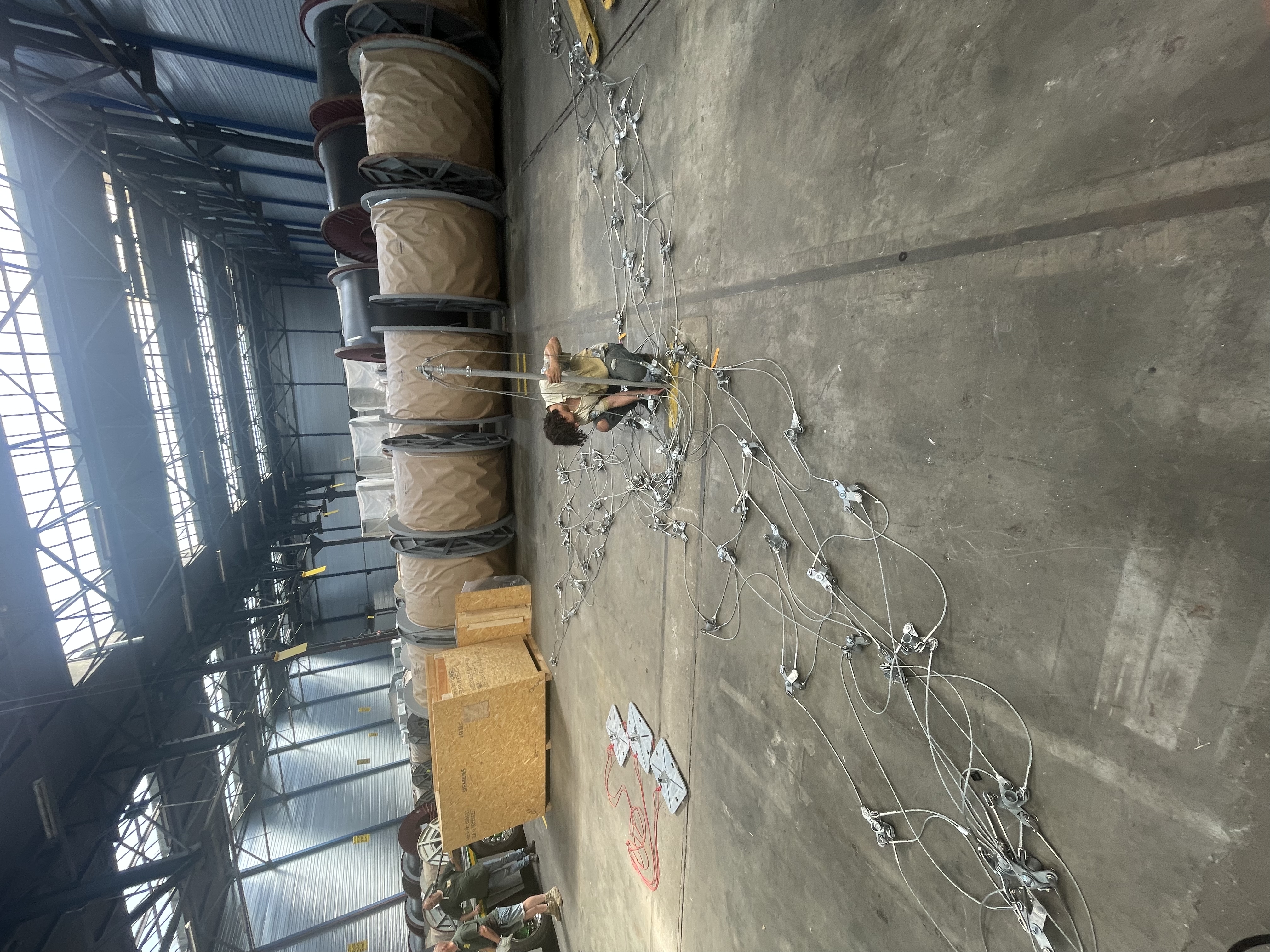
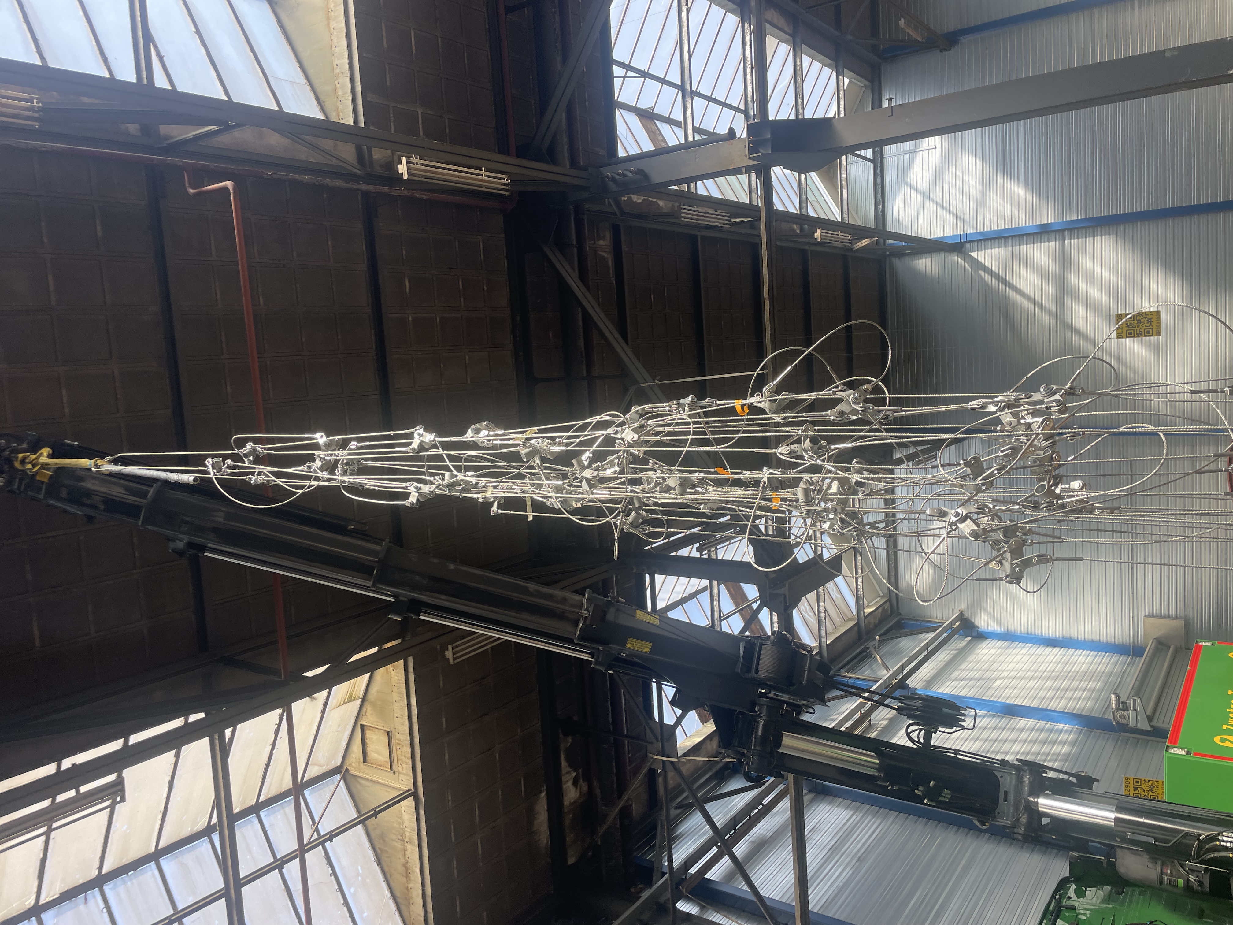
Lifting the cable network one last time to move it over and lower it into its box for transport.
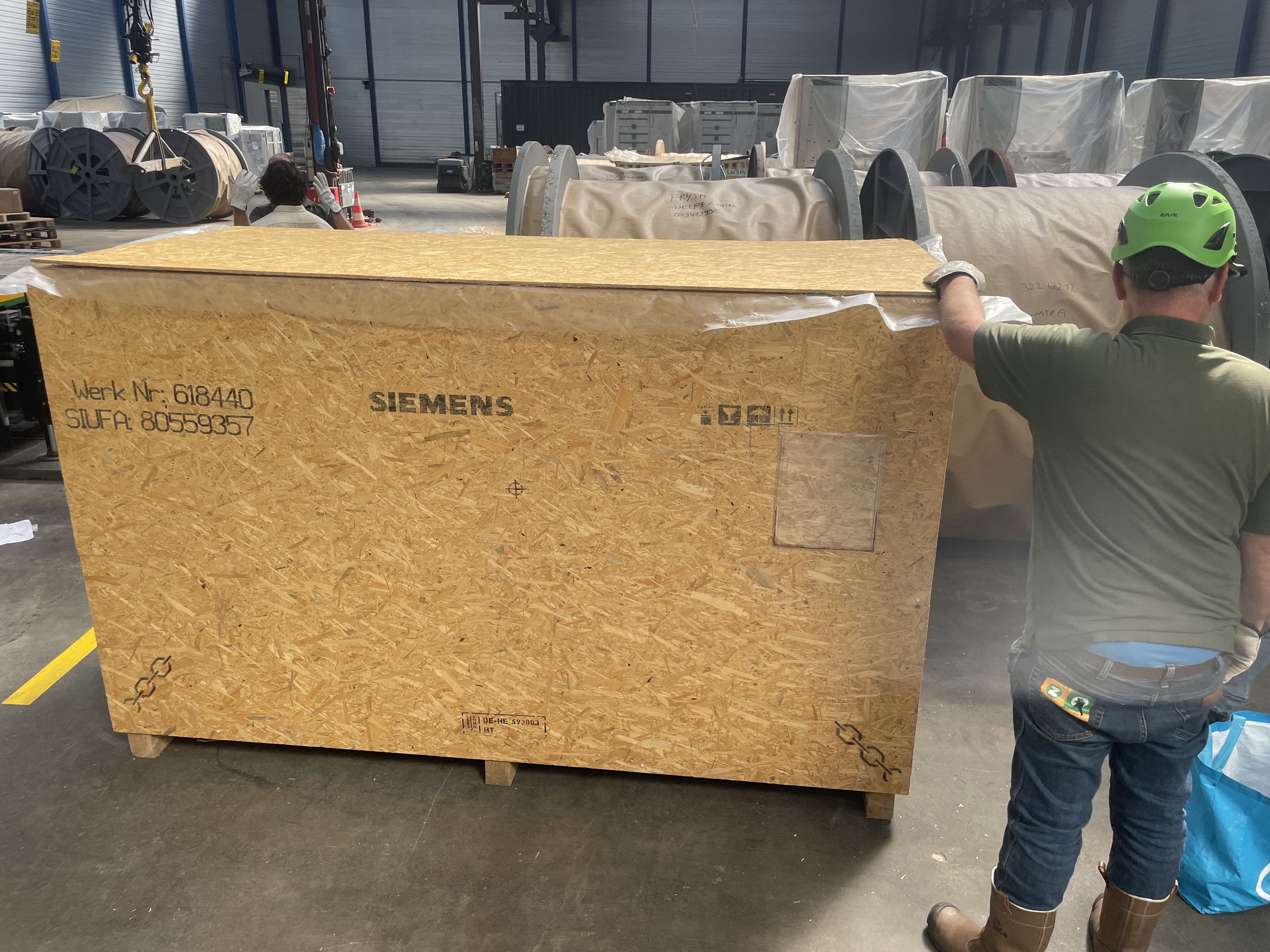
It was in the box and Zwatra delivered it that same afternoon to the festival terrain.
Onsite Build Sunday 28 June
When we opened the box, we could see that the whole structure was collapsed only into the bottom, so it wasn’t taking up much space at all. This made my main builder Kim van der Hoeven think that we could fit this whole thing into a small trailer! That will be the next approach.
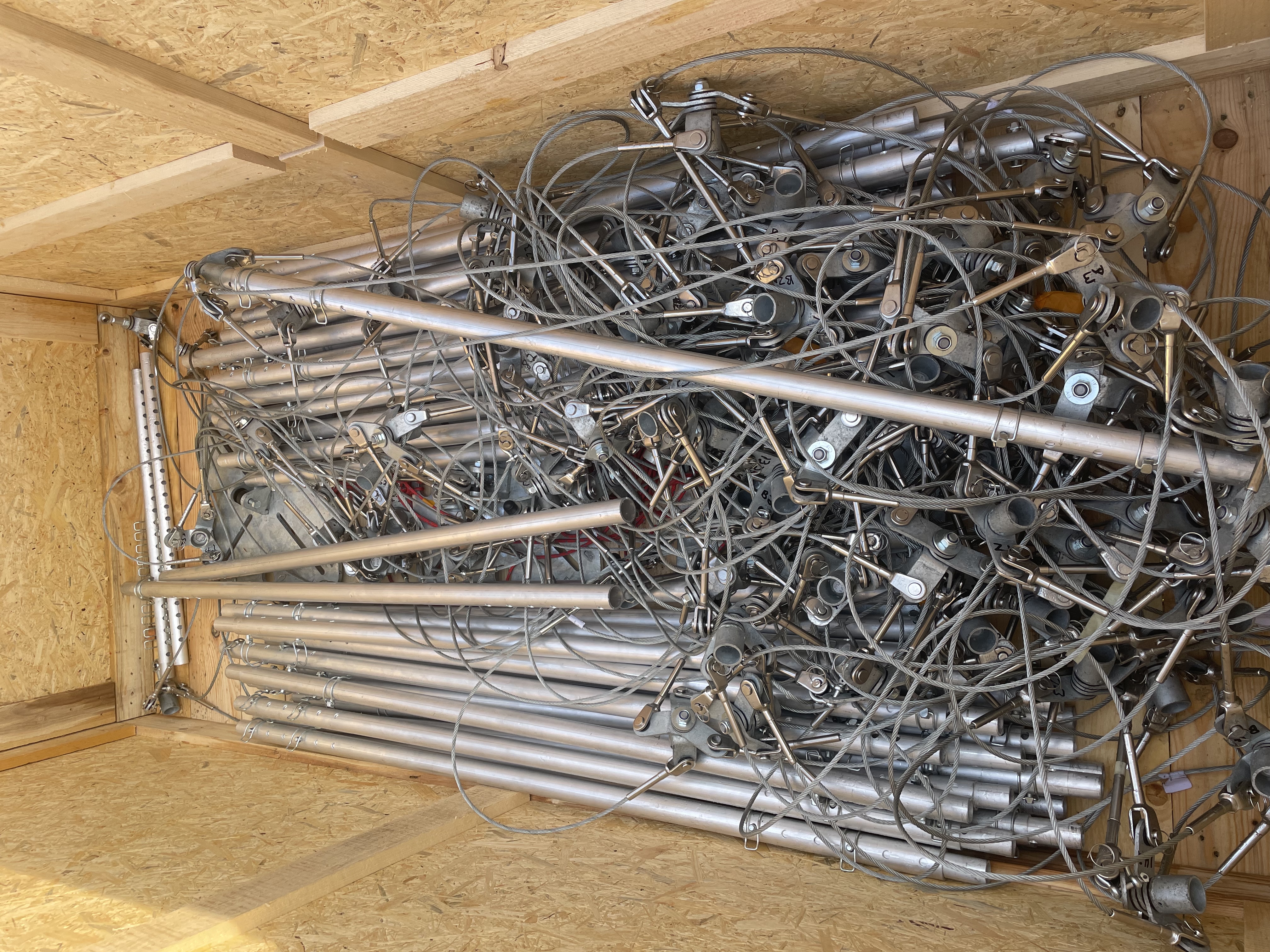
We took apart the box to use as a platform because it had rained hard the night before and the grass was very wet, almost muddy.
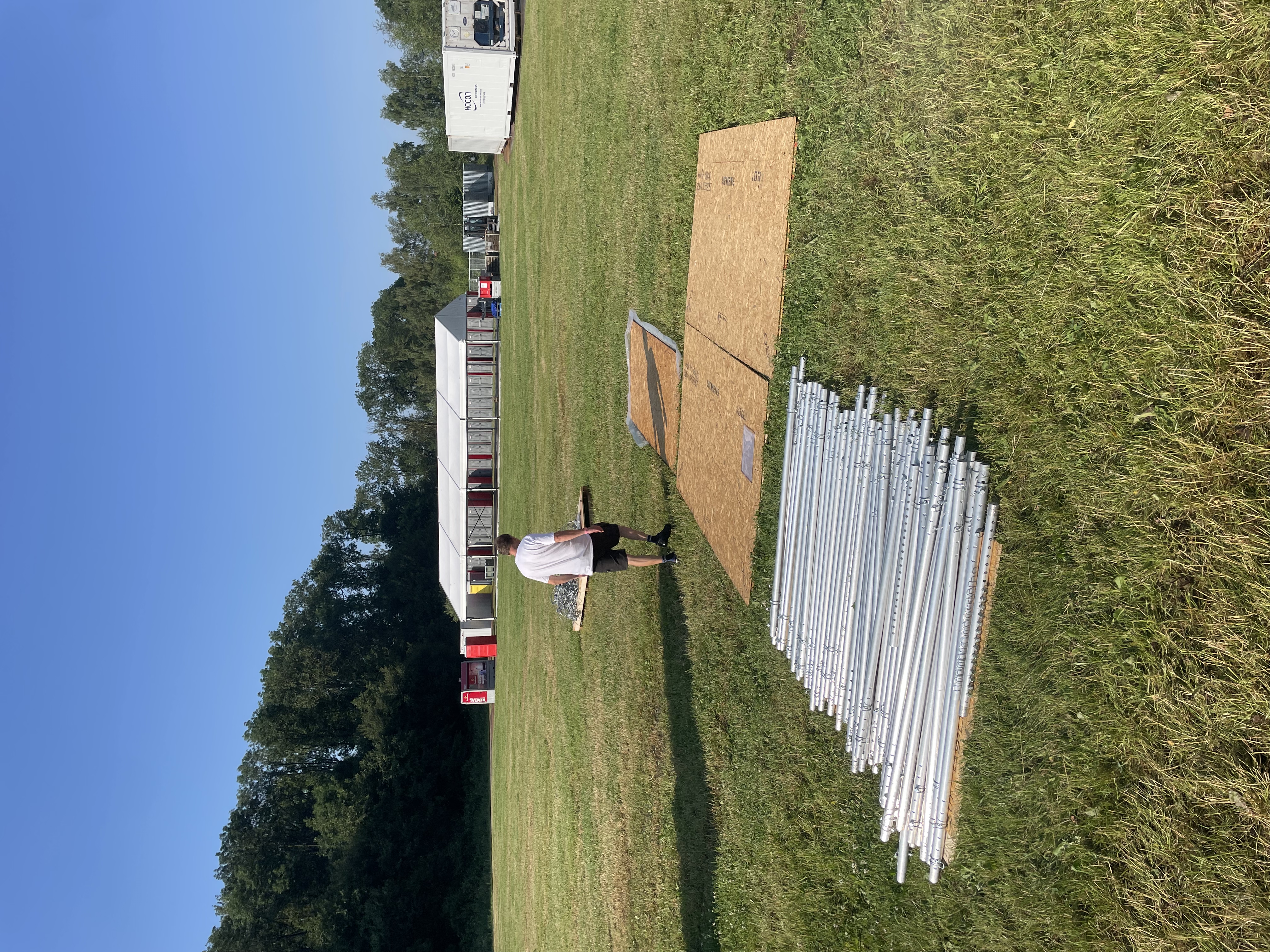
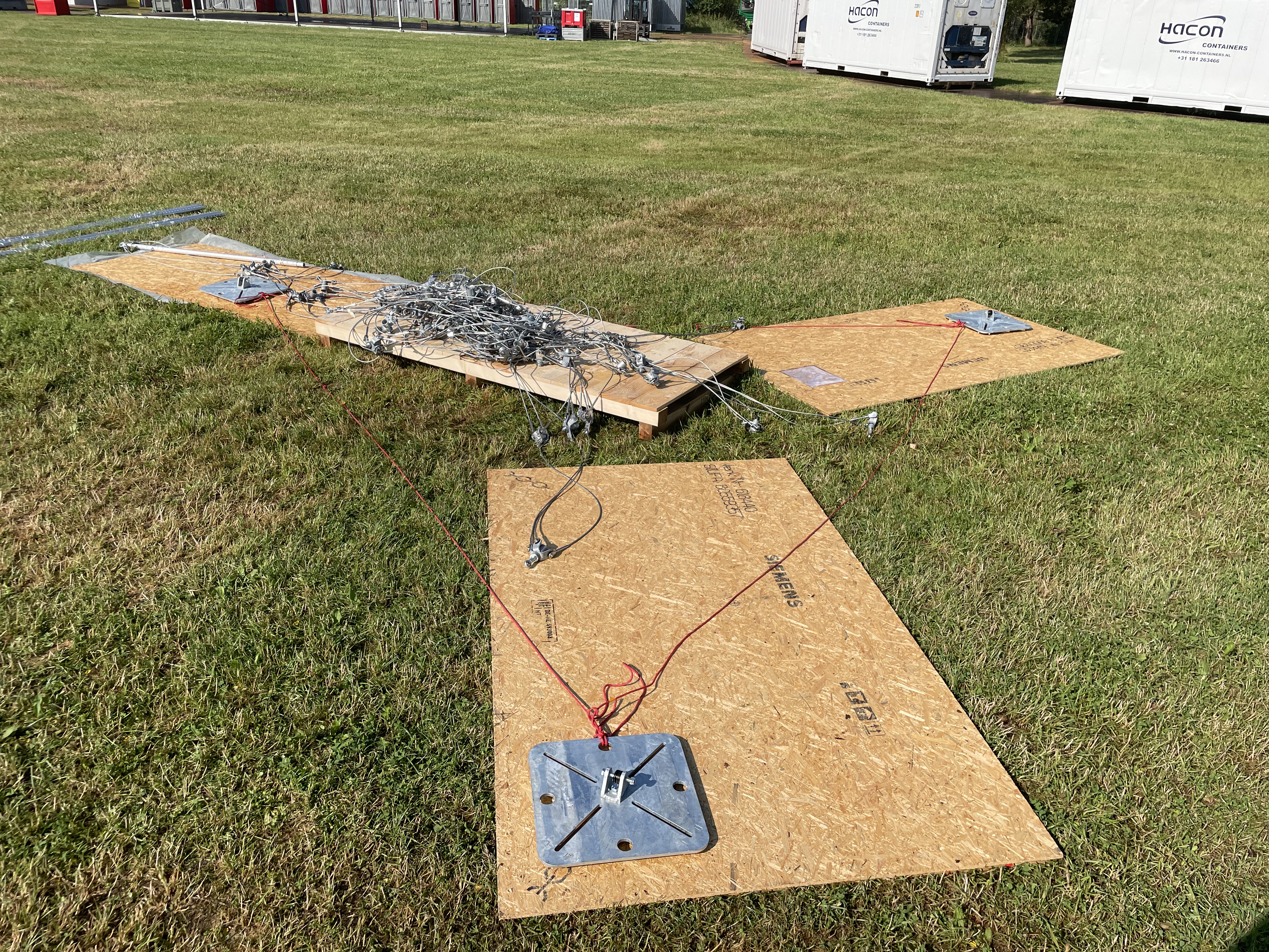
Preparing for assembly of the three-symmetry legs, we spread the box parts out and set the cable ready for when the crane arrived at about 10:45.
The crane lifted up the cable network and we rapidly adjusted struts to length and inserted them, layer by layer as the crane lifted further. This was also exactly how it looked in my simulation, so it was almost familiar despite the fact that this was the first time building this way.
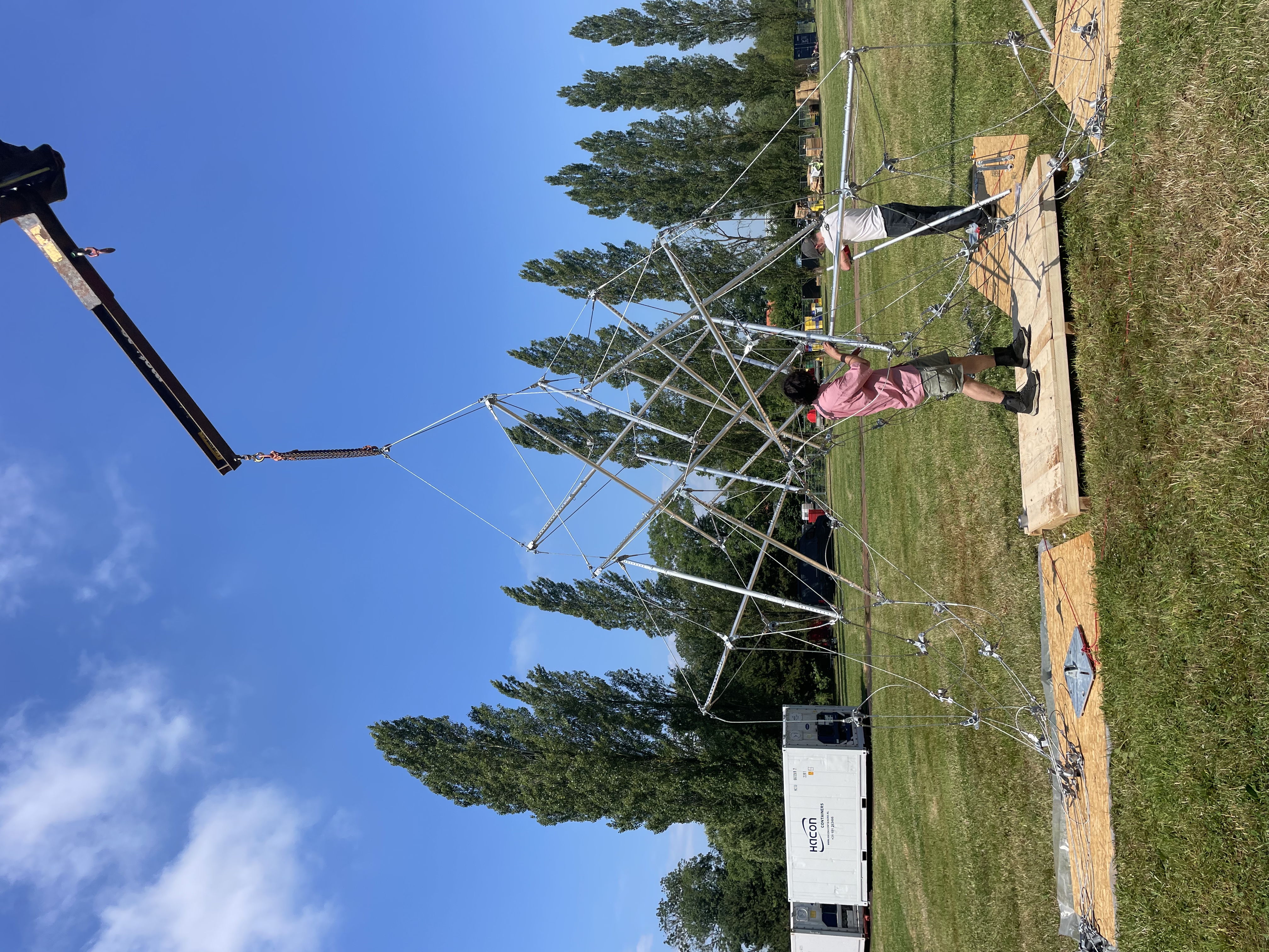
After every level, the crane went a little higher.
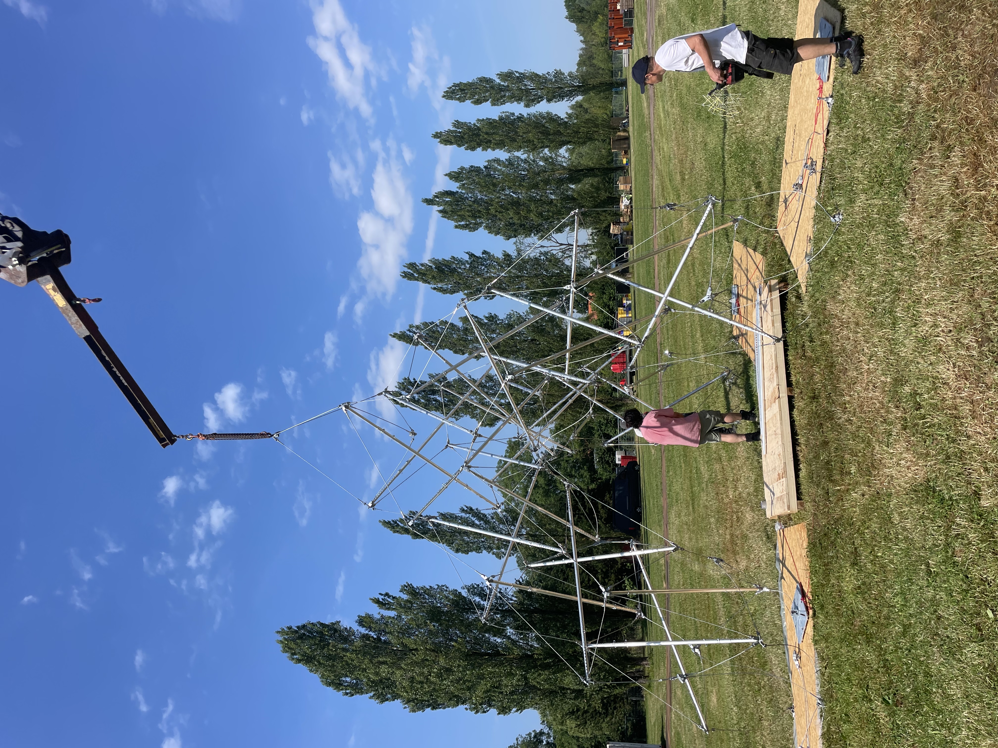
Finally, just after noon we had all the struts inserted, so it had taken about two hours from when the crane had hooked up.
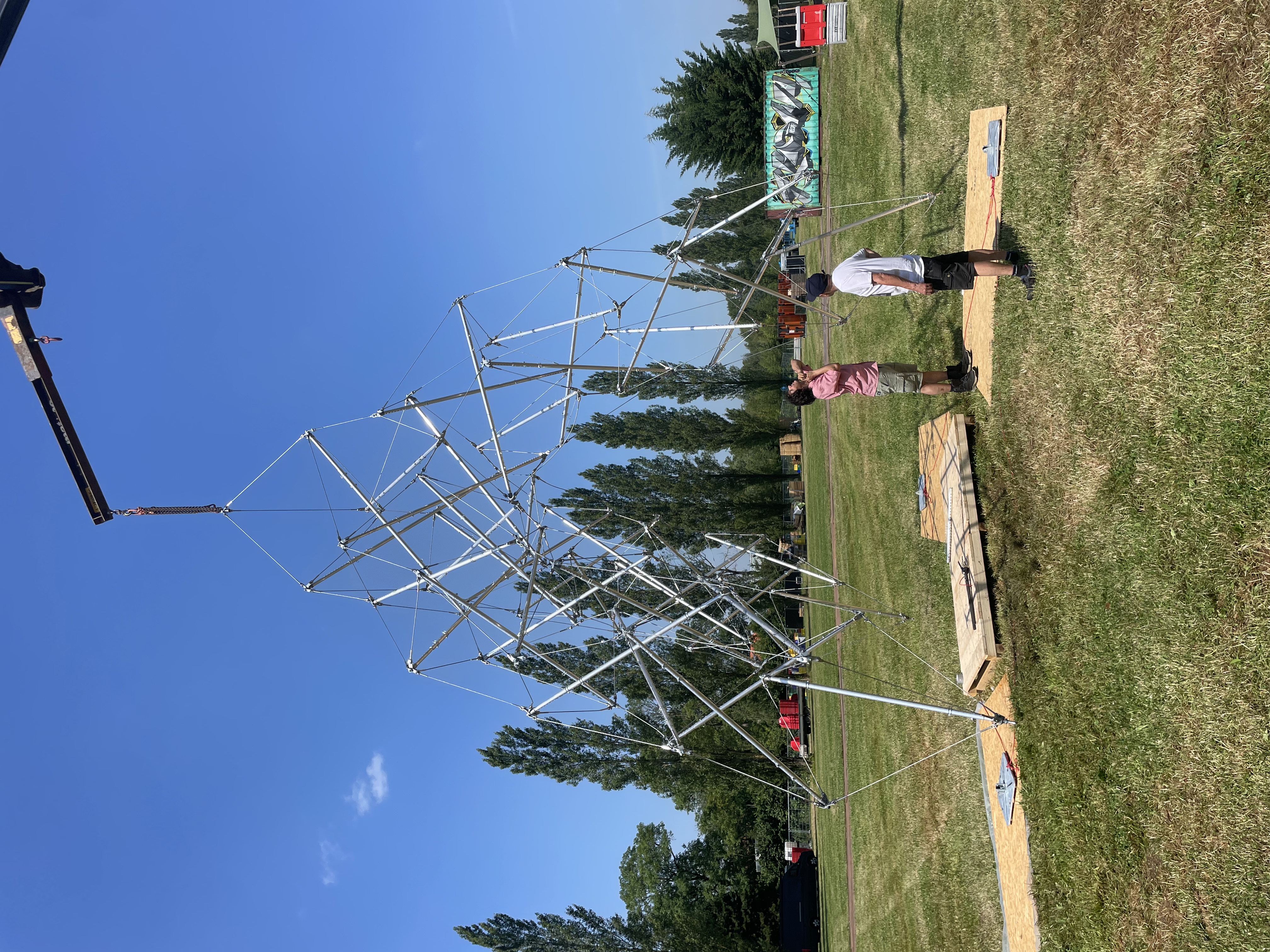
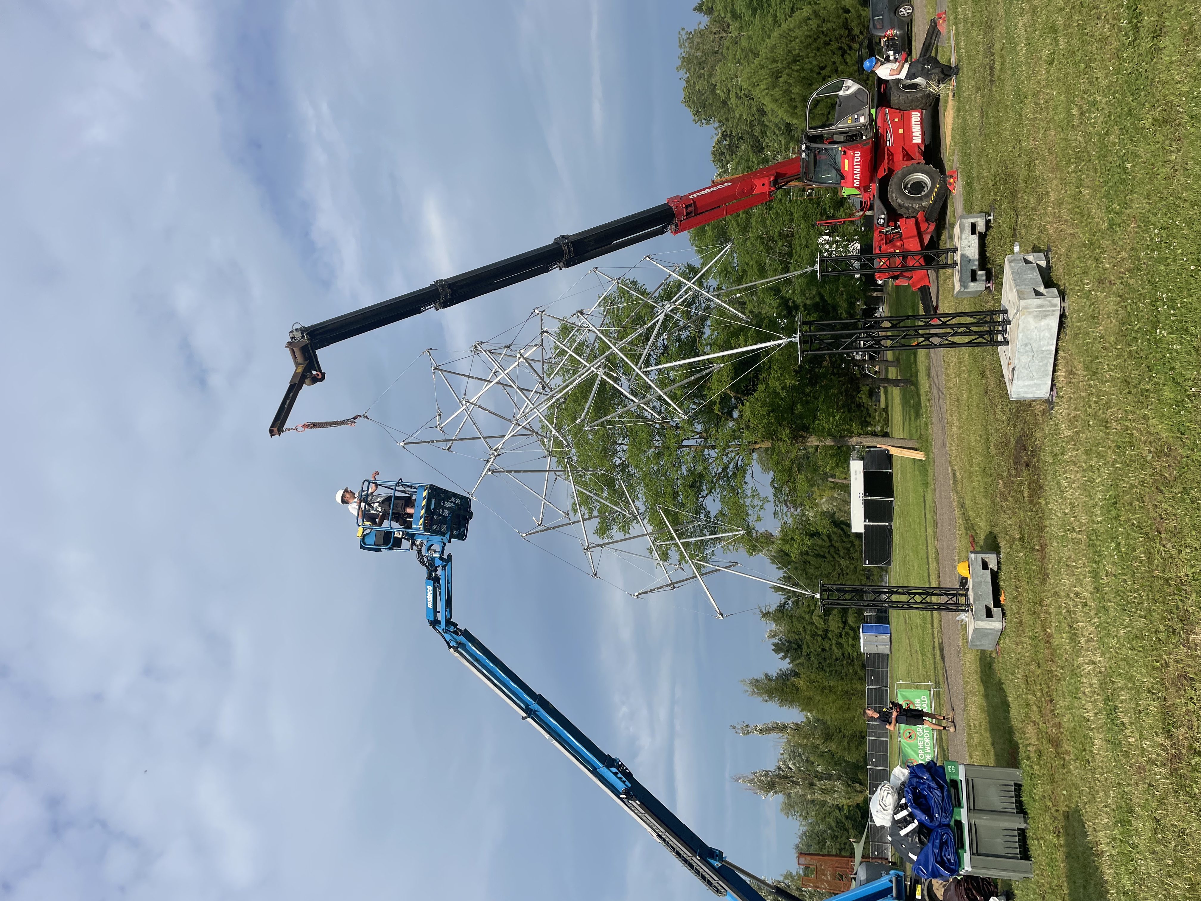
With the truss towers carefully placed at the right distances and orientations, we were ready to lift it up and connect.
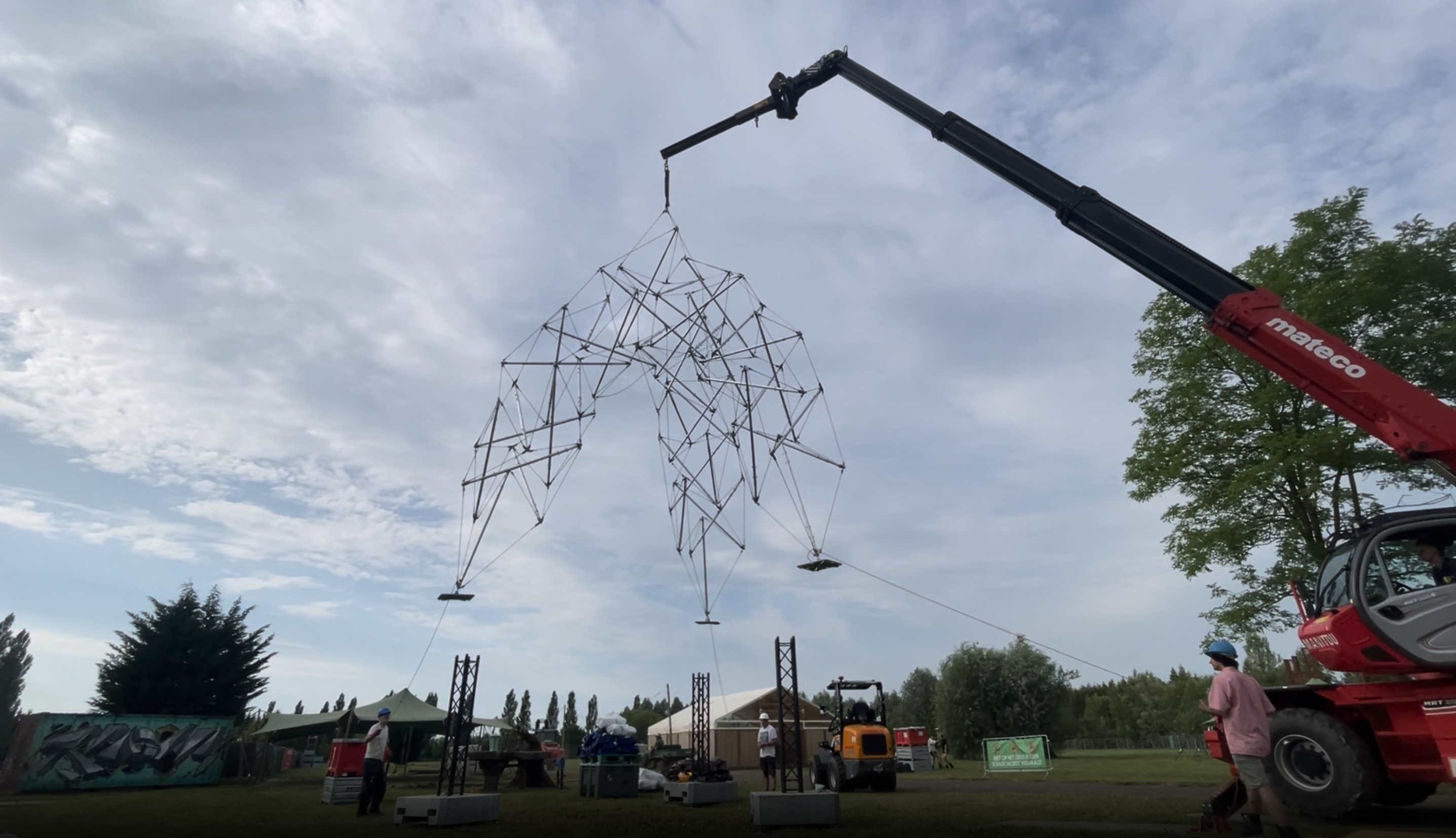
Each leg was mounted on a square base plate, which could be bolted to the top of the truss tower.
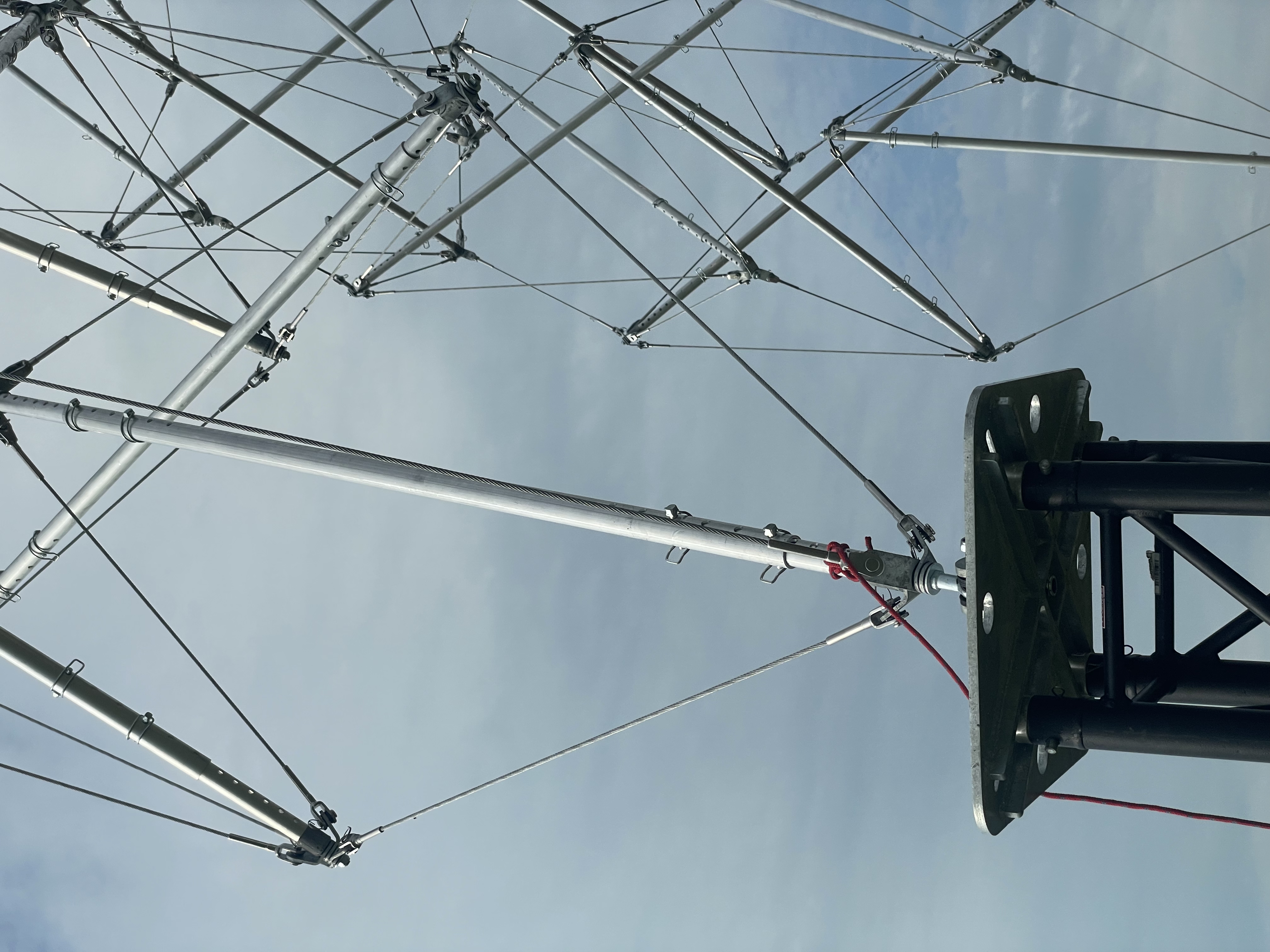
Twelve bolts, four on each base plate.
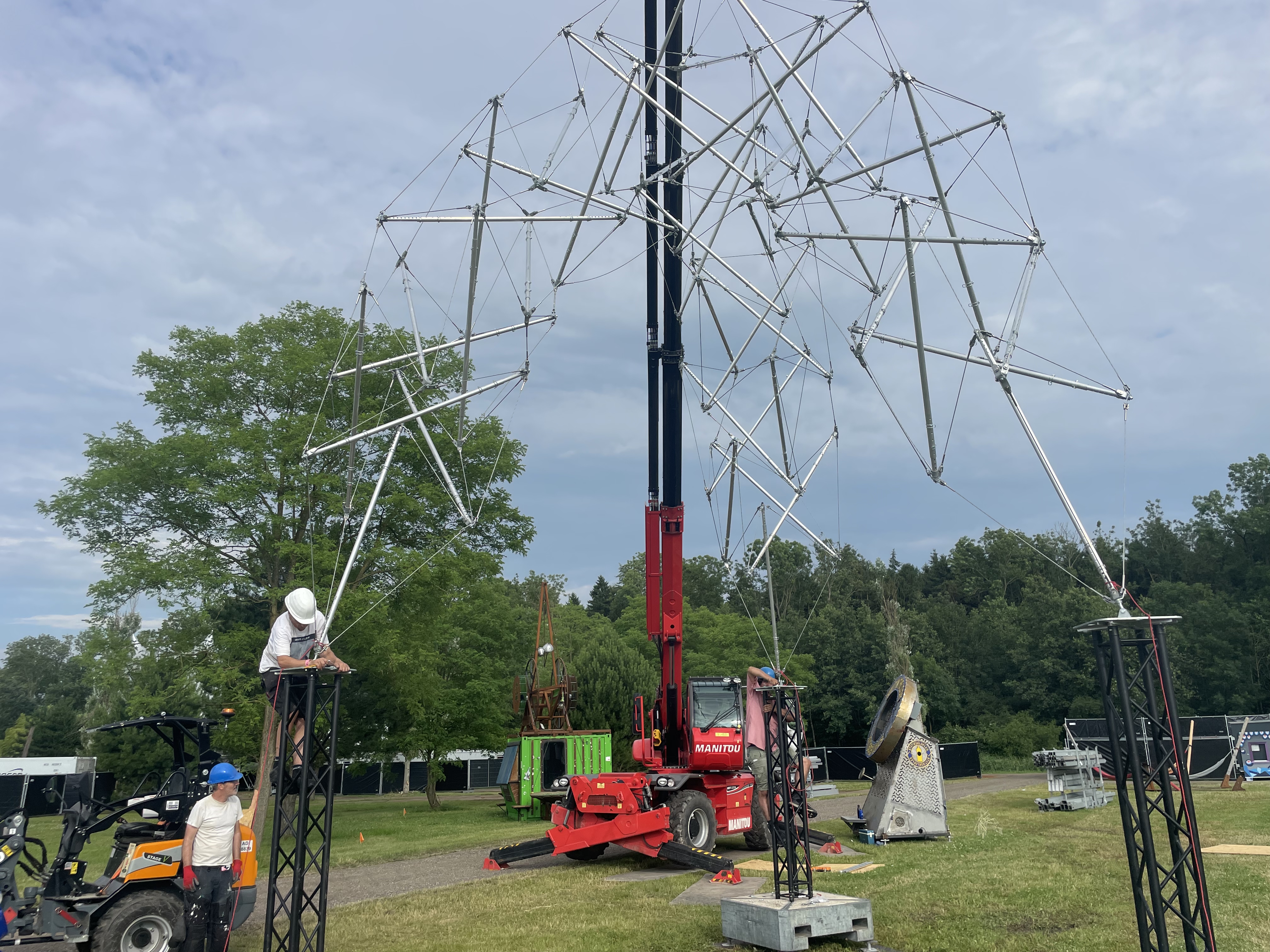
Finally, the apex strut is installed. It fell out during construction so we left it out, which we will not do next time.
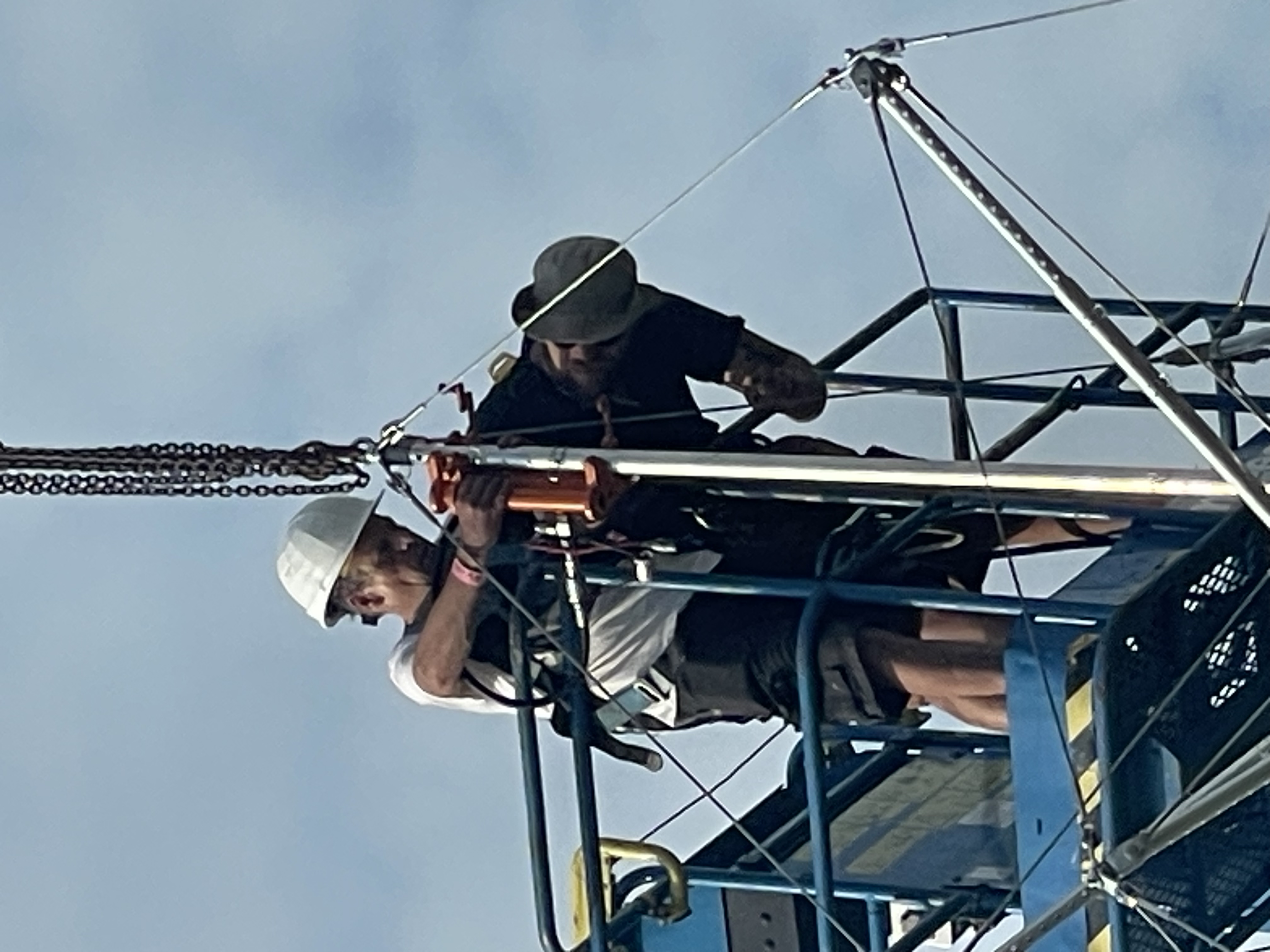
It was more difficult for Kim than we had anticipated but he was successful.
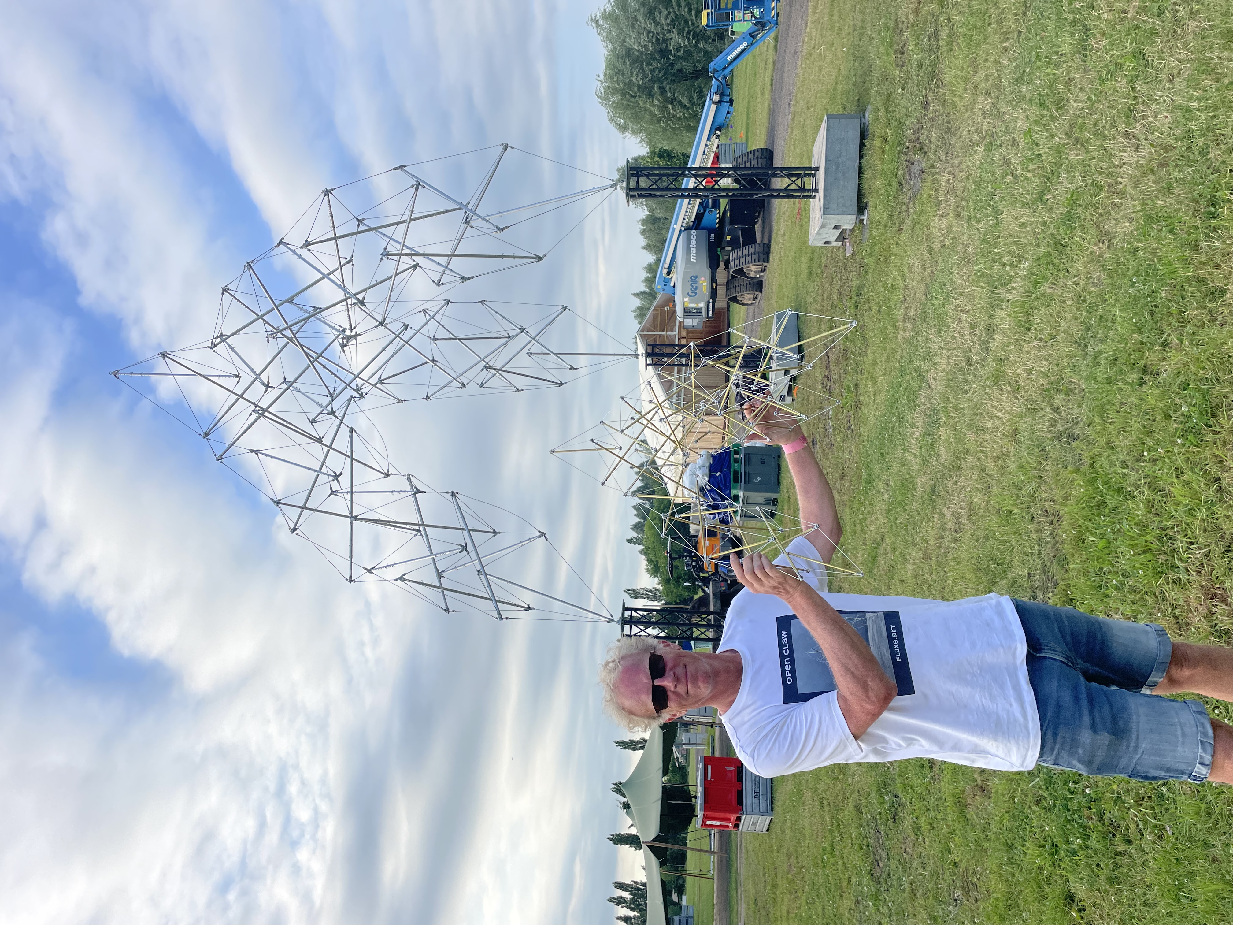
And there we have it! Ten meters tall including the truss towers, and it looks exactly like the 1:10 model that I had built in May.
The view from below, which will be even better at night when the lights are attached.
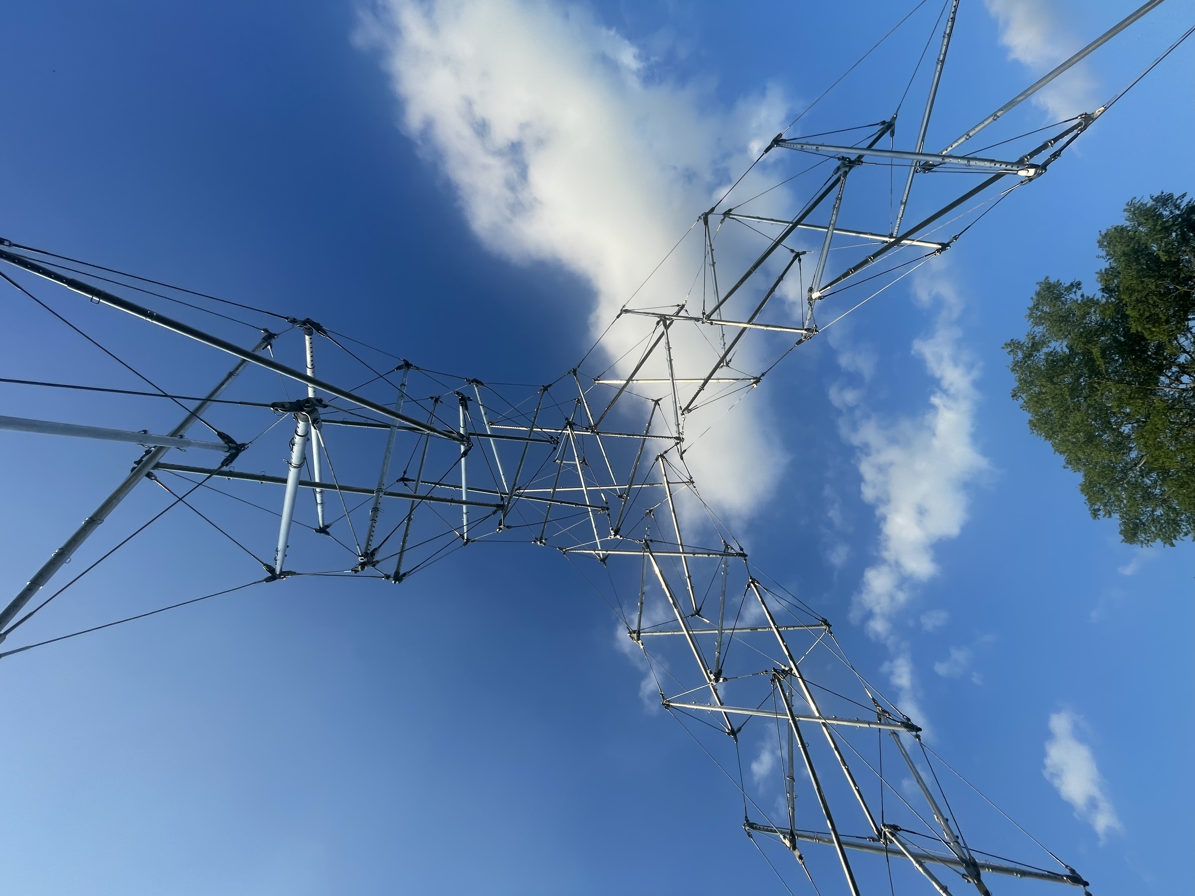
Open Claw stands! Built up from storage in a day quite easily. Next time will be easier yet as we develop the routines.
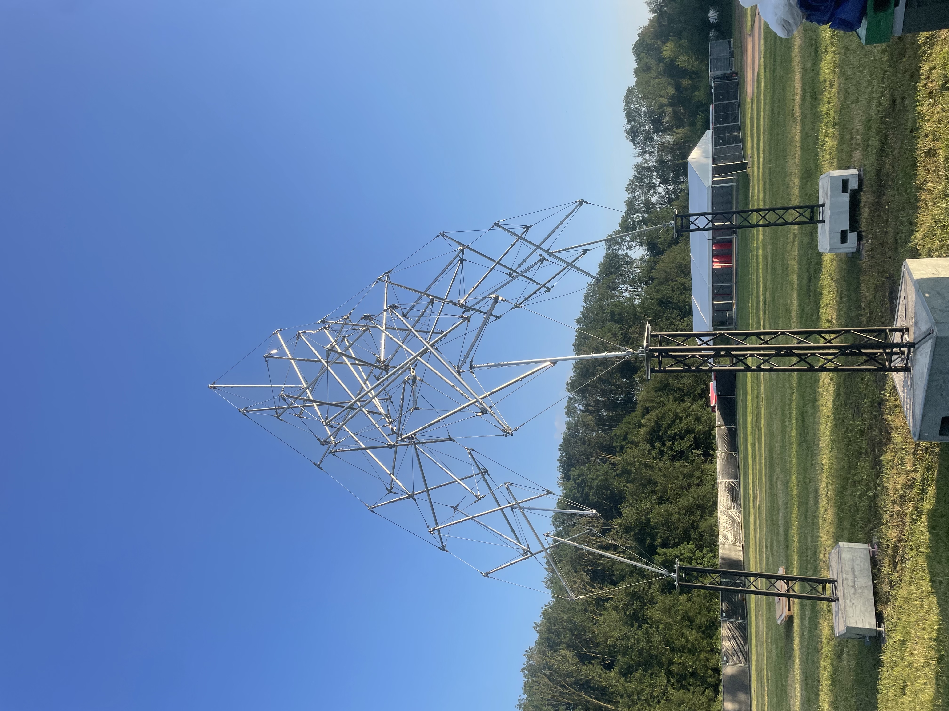
Many thanks to all the people who worked on it and volunteered for the build. I think everyone involved had a quite unforgettable experience.
This is actually something new. Large scale tensegrity which is easily made compact and transported.